I recently picked up a broken Sony bluetooth speaker locally for $20. Using a few resources I found online, I was able to easily fix the mainboard so it would turn on. Originally the speaker would show no lights at all, not respond to any buttons.
This seems like a common problem for this model, and this guide will hopefully help keep these surprisingly good sounding speakers out of the landfill.
My repair service
IF you are not comfortable working with high voltage, and soldering electrical components, I am providing a repair service for anyone who wants their board fixed. Feel free to email me at [email protected]. We will need to do some basic troubleshooting to confirm the issue is indeed something I can fix.
How to fix it yourself
(Note: Do this at your own risk. This guide may expose you to High voltage which is dangerous and I don’t take any responsibility for any damages, injury, or death).
To Fix it yourself, you will need to be skilled with a soldering iron, and have knowledge of basic electronic circuits.
Parts you’ll need (Amazon Affiliate links):
- Buck converter
- A soldering iron
- 24 Gauge wire (Wire included in soldering iron kit should work fine)
- Wire Strippers
- Electrical Tape
- Kapton tape
- Side cutters
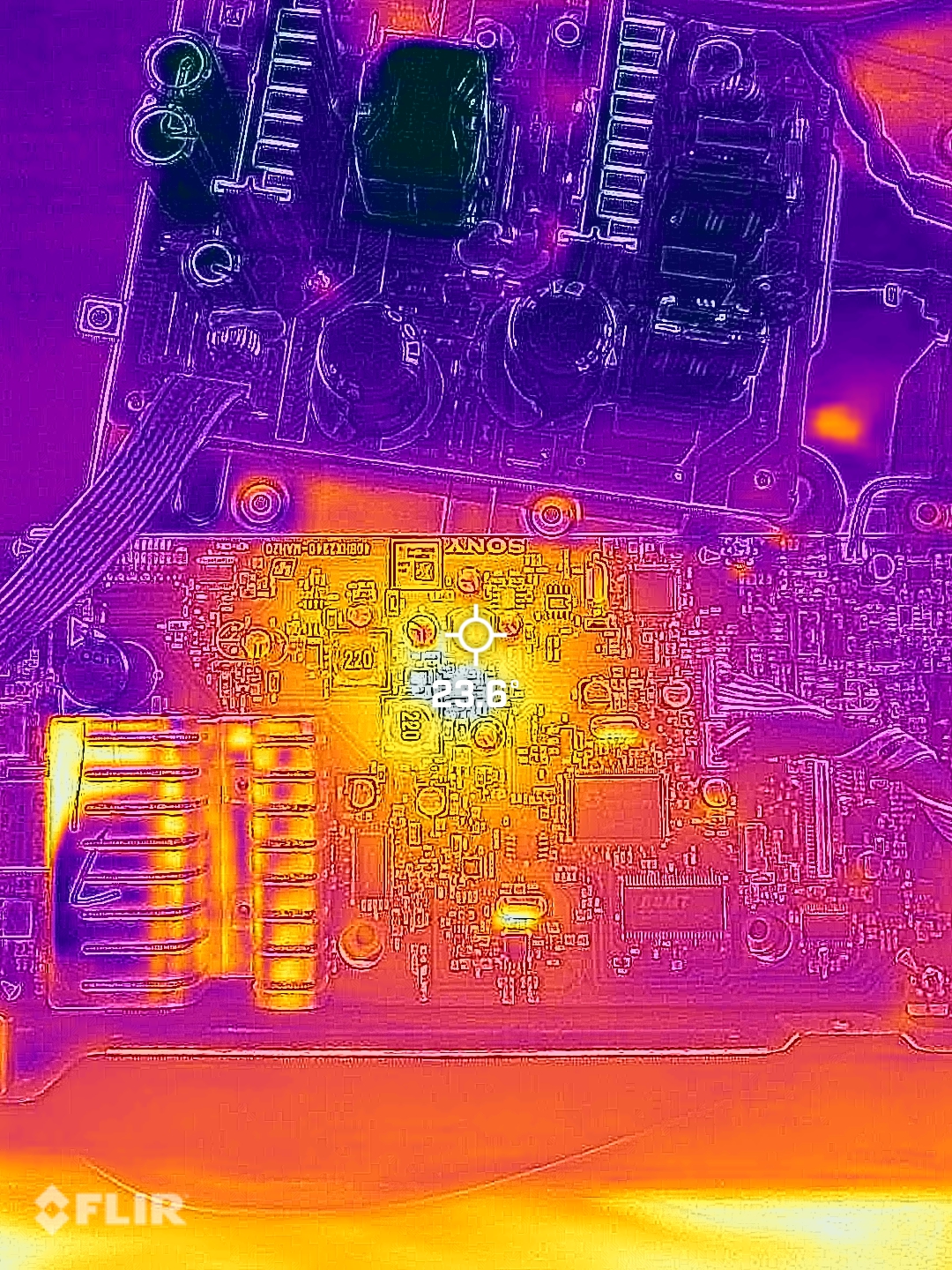
The problem with these speakers lies in the 5v power regulator IC and schottky diode. These components are prone to failure which causes the diode to dead short, and the IC to burn out. My thermal camera shows the 5v IC getting hotter than the rest of the board.
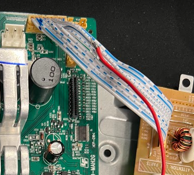
The power supply board provides 36v via a white and blue ribbon cable. This power supply is always on when AC power is provided. So if you can probe this wire and see 33-36 volts DC, your power supply is likely fine.
Rather than carefully desoldering the 5v IC and diode, then waiting possibly weeks for working replacement parts (That may end up failing again). I elected to bypass the integrated 5v circuit and use parts that you can get next day on Amazon.
Some people have found that simply replacing the SS34B diode fixed their problem, but in my case, I de-soldered and lifted the output (pin 3) of the 5V IC and found no voltage was present, telling me the chip was bad. IF your 5v is good, and the diode is bad, you can either replace it with another SS34B, or a common 1N5822 through-hole style diode
The easiest way to remove the 5V IC is to use your side cutters to cut the legs off of the chip (Labeled U3 on the board). You will not be able to completely remove the IC from the board without a hot air station. The bottom of the chip is a ground and soldered to the PCB.
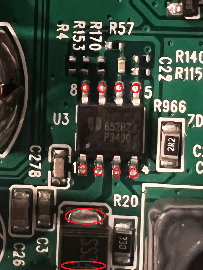
Now, de-solder the schottky SS34B diode(D1)
Find or purchase an off the shelf buck converter from a site like Amazon. I used this one
Strip some wire off of the 36v ribbon cable to solder a wire that will go to the “V+ In” on the buck converter.
Solder a wire onto the Anode side of ZD2. (You’ll see the diode, blue and orange next to the inductor labeled 220). Solder this wire to the “V- In” on the buck converter.
Turn the power supply on, and use the trim pot to adjust the output voltage to 5.00v DC.
Once you have voltage dialed in, solder a new wire onto the Cathode(blue) side of ZD2. Solder the other end of this wire to “V+ Out”
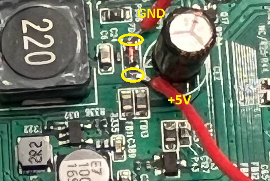
We are essentially bypassing the burnt out 5v circuit and replacing it with a buck converter.
Use Kapton tape to tape down the wires and prevent any movement or stress to the parts you soldered
Use electrical tape to cover the spliced 36v ribbon cable
Reassemble the board and test.
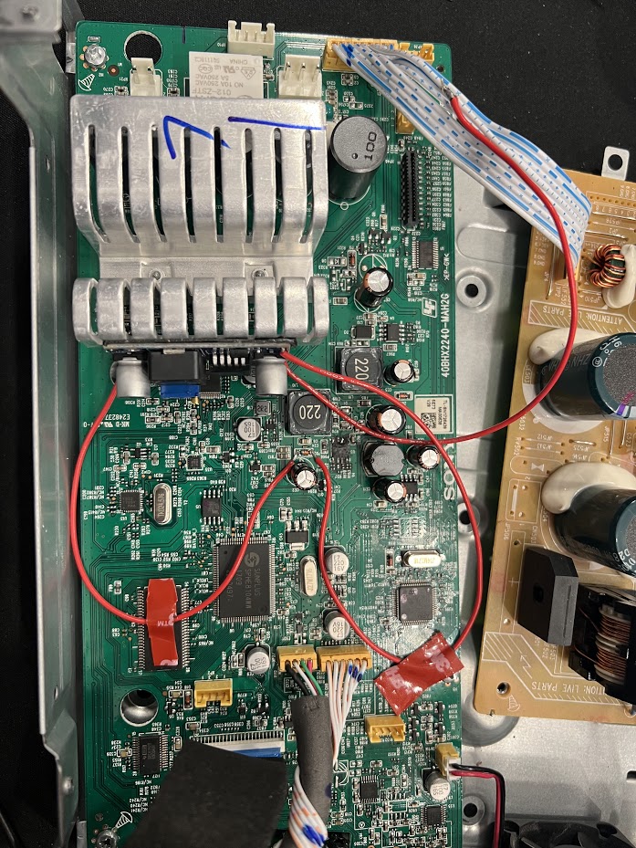
Board works.
Reassembled everything, tested all the functions including the app and remote control. No issues.