

Honda Goldwing Poor Boy Alternator parts list 2025
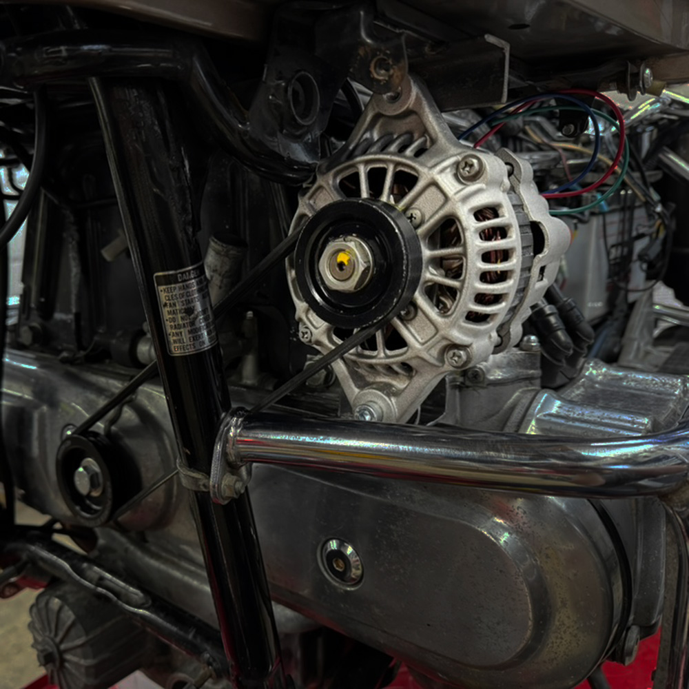
I just completed a poor boy alternator on my Honda Goldwing GL1200 Aspencade. I tried my best to document any tips and all the parts I purchased to complete the project below. Youtube Video: https://tinyurl.com/poorboy-alt This document uses affiliate links, and I earn a small commission when you purchase parts using the links on this…