File to make it yourself: XG-100P-AccCover-v6.stl
Hardware needed: M3x6 hex cap screw
File to make it yourself: XG-100P-AccCover-v6.stl
Hardware needed: M3x6 hex cap screw

I just completed a poor boy alternator on my Honda Goldwing GL1200 Aspencade. I tried my best to document any tips and all the parts I purchased to complete the project below.
Youtube Video: https://tinyurl.com/poorboy-alt

This document uses affiliate links, and I earn a small commission when you purchase parts using the links on this page.
Finding the device ID for Exchange when you use the native mail app for iOS is fairly straightforward, but if you use the Outlook for iOS app, it is much harder to find.
I’ve discovered a process to uncover the device ID, because it appears to be hidden from the Outlook app alltogether.
See this screenshot from an Outlook App device in Exchange Online. Compare it to the one below it of a device added with the native mail app.
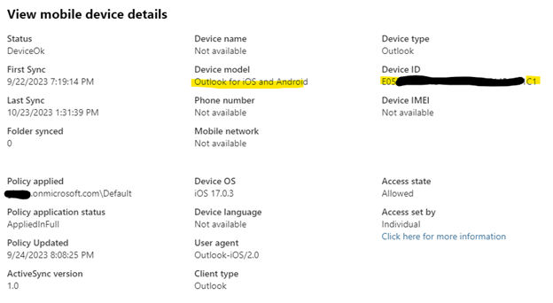
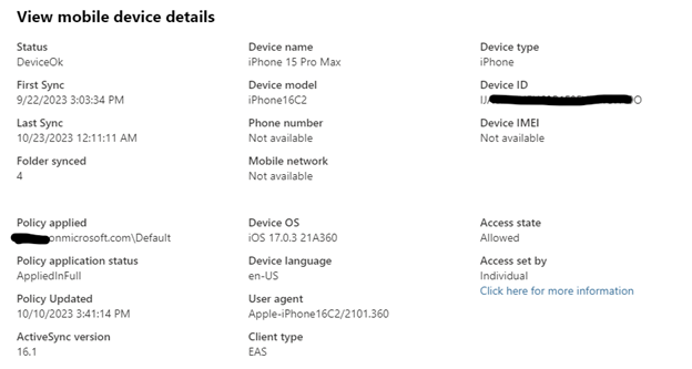
The native mail app gives you more detail, which can help you identify the correct device easier. The Outlook app has almost no information besides the iOS version which is usually outdated.
We can get the device ID from your device that uses the Microsoft Outlook App, but you need to perform some additional steps.
You will need a Windows PC with the Microsoft store to download the Microsoft Diagnostic Data Viewer The mobile device in question must be connected to the same Wireless network as the diagnostic PC. The outlook app will create a TCP connection to the PC to send logs.
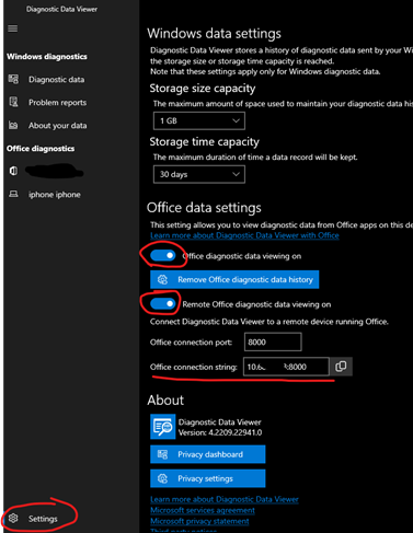
Download Microsoft Diagnostic Data Viewer on PC
Go into Settings and enable Office diagnostic data viewing on, and Remote Office diagnostic data viewing on
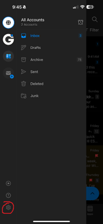
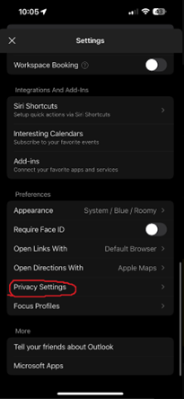
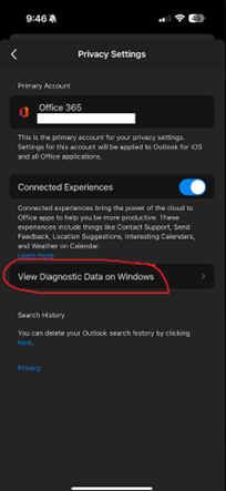
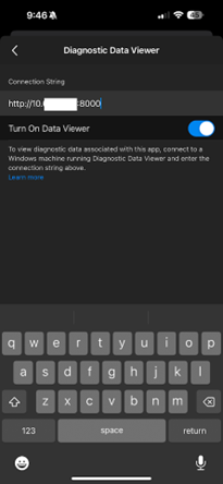
Open the Outlook App and go into Settings>Privacy Settings>View Diagnostic Data on Windows
Copy the Office Connection String from the Diagnostic Data Viewer, and enter it into the Connection String field on the Outlook App.
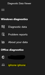
Exit back to the main screen of Outlook, and check for new messages by pulling down on the Inbox screen. You should see your mobile device show up on the sidebar of the Diagnostic Data Viewer
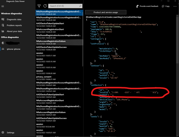
Select this device, and you should see JSON debugging information. This localId matches what we see in Exchange Admin Center
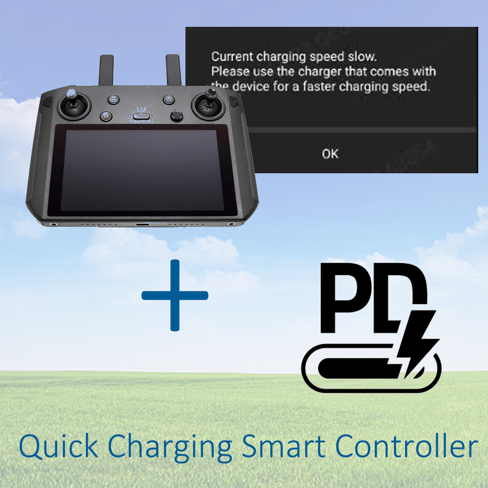
If you own a DJI Smart Controller, you may have come across this message while trying to plug it in to charge.
Current charging speed slow. Please use the charger that comes with the device for a faster charging speed.
Slow charging a smart controller could represent a hazard, because the slow charge rate isn’t enough power to maintain the battery level while flying your drone.
After a recent incident where the smart controller shut down while I was flying a drone, I became determined to find a solution to be able to rapid charge the controller via a battery pack I already had
A forum post I discovered mentioned the controller used Qualcomm’s QuickCharge standard. Qualcomm’s QuickCharge standard is a pre-USB PD era charging standard that allows negotiated charging above 5v for supported devices.
I didn’t want to buy yet another battery pack just for an antiquated standard, so I opted to make a cable that converts USB PD to QC instead.
Parts list (Amazon Affiliate links):
Consumables I already had:
Tools:
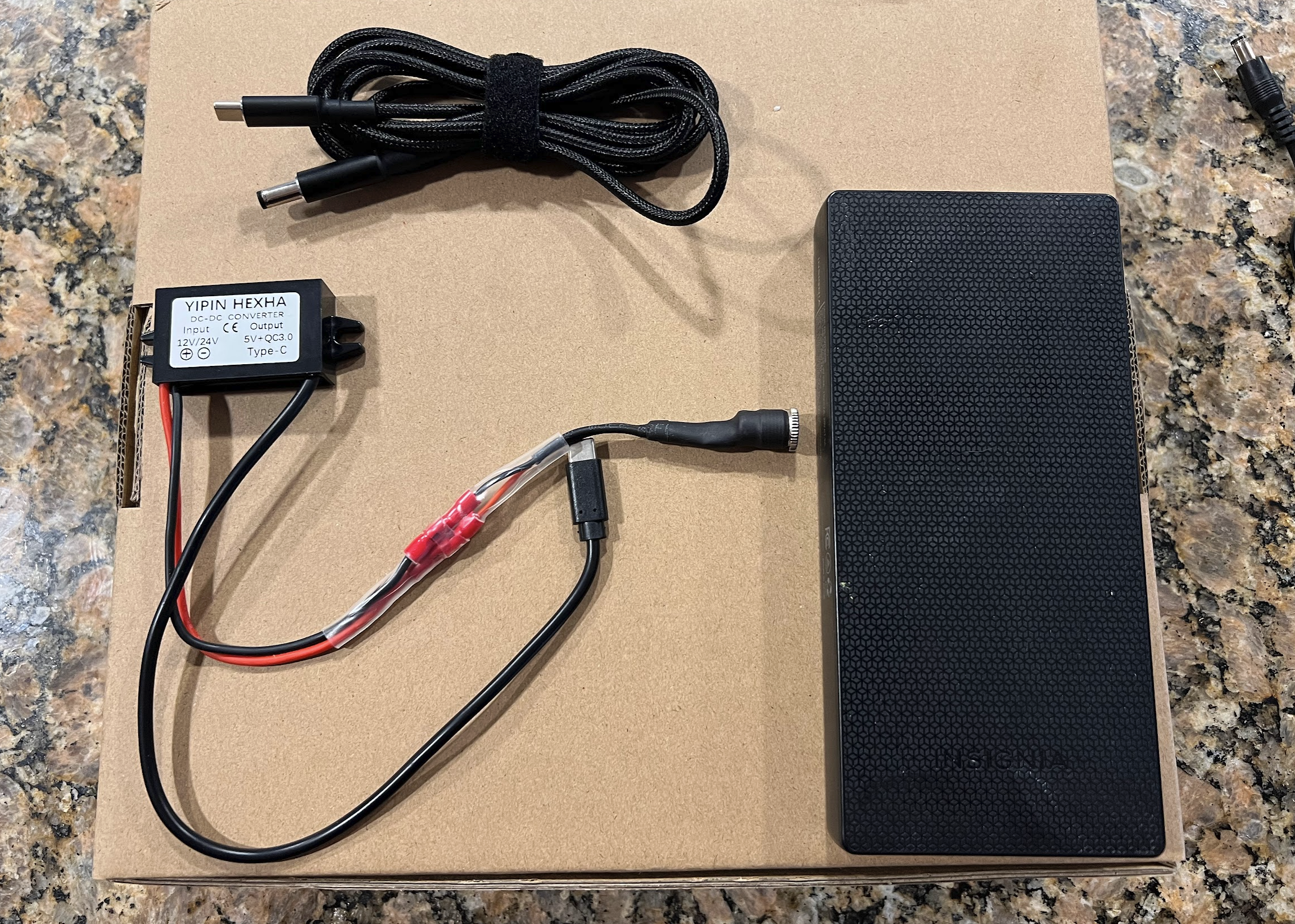
Here is the final product:
The braided cord goes into the battery pack, and the barrel plug goes into the QC 3.0 adapter. This braided cord is the magic sauce that tells the charger to output 20v, and send that to the “yipin Hexha” adapter
That adapter will let you charge your Smart Controller significantly faster than before, and your controller won’t die while charging. Hope this helps!
I recently picked up a broken Sony bluetooth speaker locally for $20. Using a few resources I found online, I was able to easily fix the mainboard so it would turn on. Originally the speaker would show no lights at all, not respond to any buttons.
This seems like a common problem for this model, and this guide will hopefully help keep these surprisingly good sounding speakers out of the landfill.
IF you are not comfortable working with high voltage, and soldering electrical components, I am providing a repair service for anyone who wants their board fixed. Feel free to email me at [email protected]. We will need to do some basic troubleshooting to confirm the issue is indeed something I can fix.
(Note: Do this at your own risk. This guide may expose you to High voltage which is dangerous and I don’t take any responsibility for any damages, injury, or death).
To Fix it yourself, you will need to be skilled with a soldering iron, and have knowledge of basic electronic circuits.
Parts you’ll need (Amazon Affiliate links):
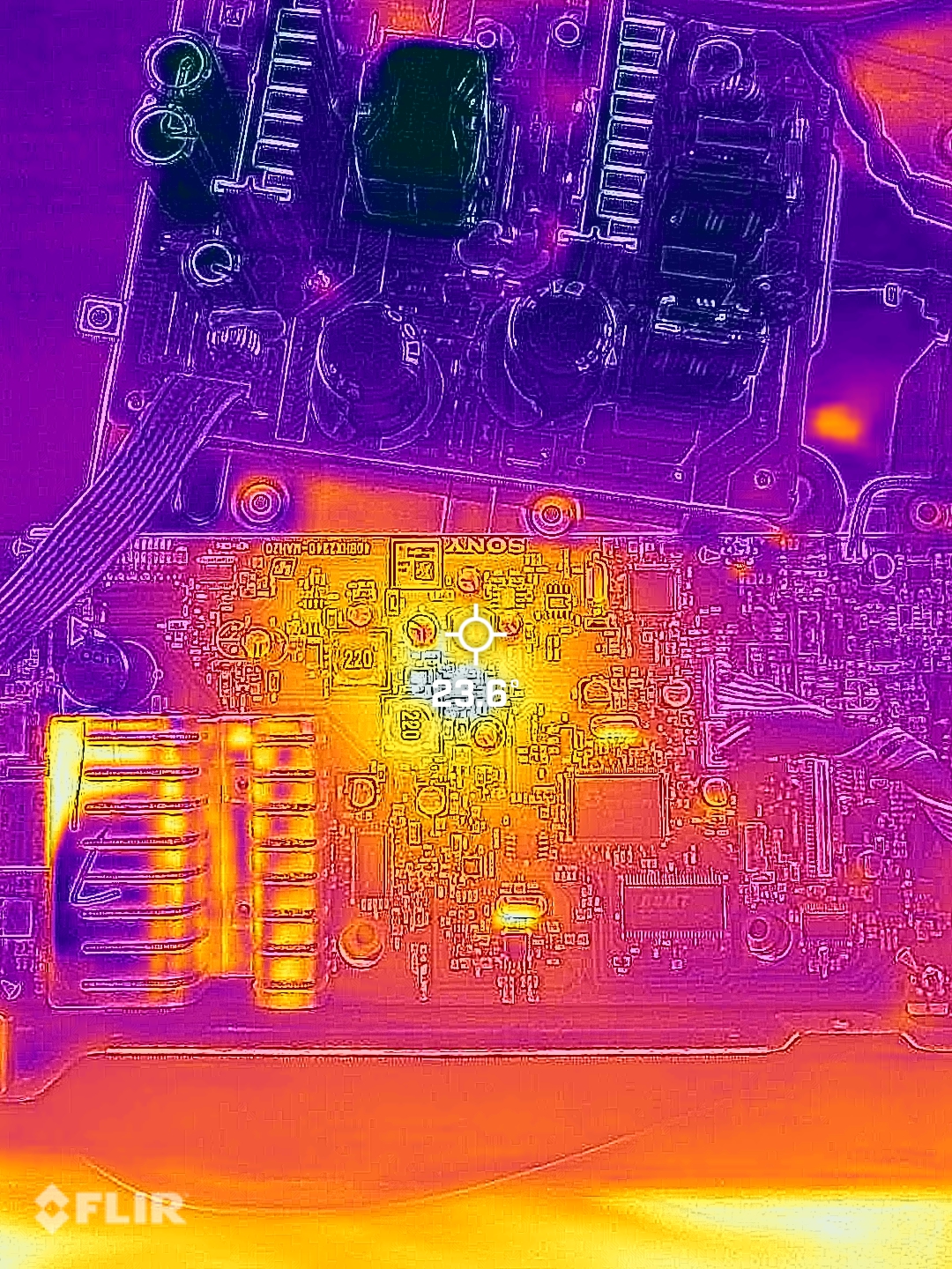
The problem with these speakers lies in the 5v power regulator IC and schottky diode. These components are prone to failure which causes the diode to dead short, and the IC to burn out. My thermal camera shows the 5v IC getting hotter than the rest of the board.
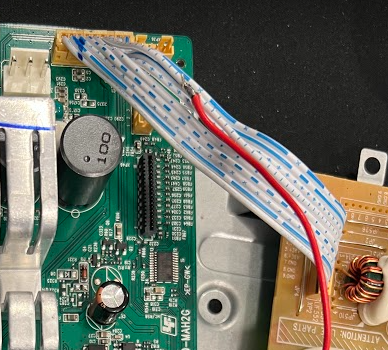
The power supply board provides 36v via a white and blue ribbon cable. This power supply is always on when AC power is provided. So if you can probe this wire and see 33-36 volts DC, your power supply is likely fine.
Rather than carefully desoldering the 5v IC and diode, then waiting possibly weeks for working replacement parts (That may end up failing again). I elected to bypass the integrated 5v circuit and use parts that you can get next day on Amazon.
Some people have found that simply replacing the SS34B diode fixed their problem, but in my case, I de-soldered and lifted the output (pin 3) of the 5V IC and found no voltage was present, telling me the chip was bad. IF your 5v is good, and the diode is bad, you can either replace it with another SS34B, or a common 1N5822 through-hole style diode
The easiest way to remove the 5V IC is to use your side cutters to cut the legs off of the chip (Labeled U3 on the board). You will not be able to completely remove the IC from the board without a hot air station. The bottom of the chip is a ground and soldered to the PCB.
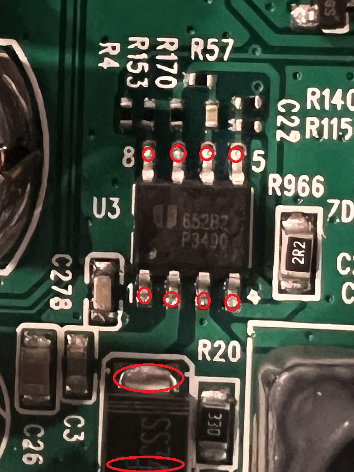
Now, de-solder the schottky SS34B diode(D1)
Find or purchase an off the shelf buck converter from a site like Amazon. I used this one
Strip some wire off of the 36v ribbon cable to solder a wire that will go to the “V+ In” on the buck converter.
Solder a wire onto the Anode side of ZD2. (You’ll see the diode, blue and orange next to the inductor labeled 220). Solder this wire to the “V- In” on the buck converter.
Turn the power supply on, and use the trim pot to adjust the output voltage to 5.00v DC.
Once you have voltage dialed in, solder a new wire onto the Cathode(blue) side of ZD2. Solder the other end of this wire to “V+ Out”
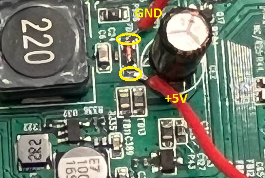
We are essentially bypassing the burnt out 5v circuit and replacing it with a buck converter.
Use Kapton tape to tape down the wires and prevent any movement or stress to the parts you soldered
Use electrical tape to cover the spliced 36v ribbon cable
Reassemble the board and test.
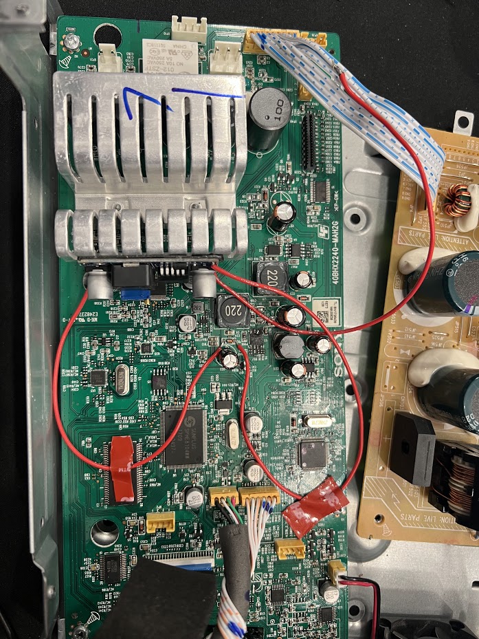
Board works.
Reassembled everything, tested all the functions including the app and remote control. No issues.

This guide will show you the fuse locations and equipment needed to hardwire a radar detector or dashcam on a 2022 Hyundai Elantra N
Consumables needed: Micro2 Fuse Tap (Affiliate Link)
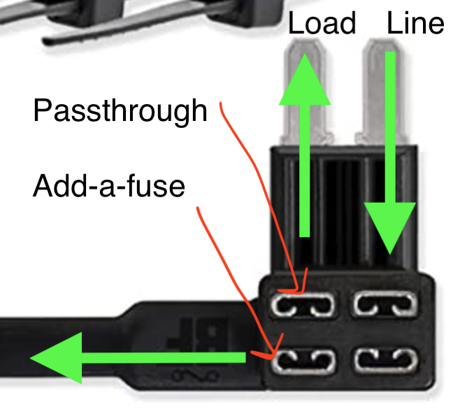
Note: Fuse Taps are directional! For unpopulated fuse banks, only put a fuse in the top and leave the passthrough spot empty.
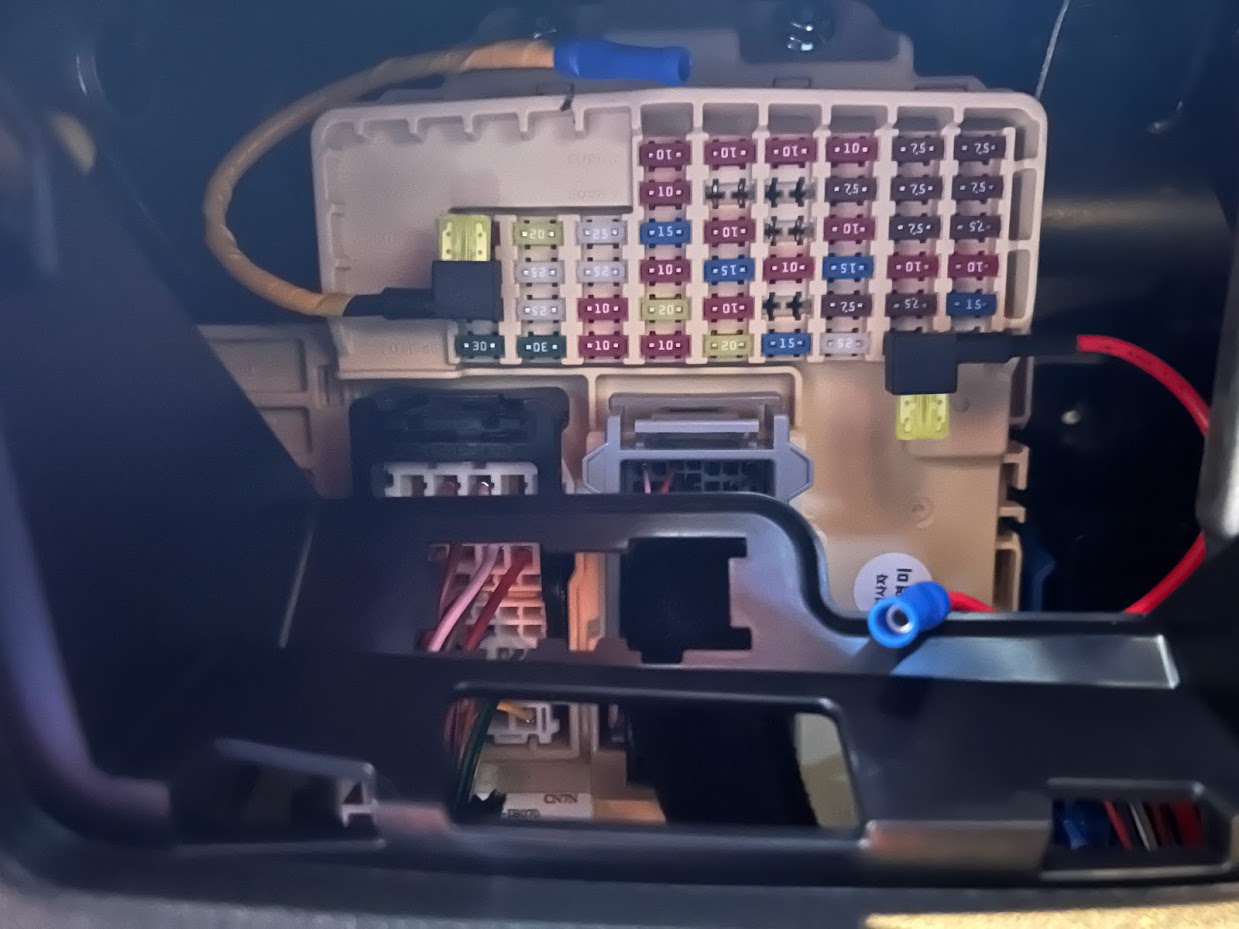
Fuse Locations
Fuse 47 (red wire on right) should be unpopulated. The left side will provide +12V when the car is on. Insert the fuse tap with the fuse facing down. You can use this for Radar Detectors, Remote wire for amp turn on, Dashcam, etc.
Fuse 31 (yellow wire on left) will provide the car +12v at all times. You can use this for parking mode wire
Ground Location

To allow an Allworx phone system to receive updates the following IP’s must be unblocked:
allworxportal.com (52.191.116.193)
TCP/8081
TCP/80

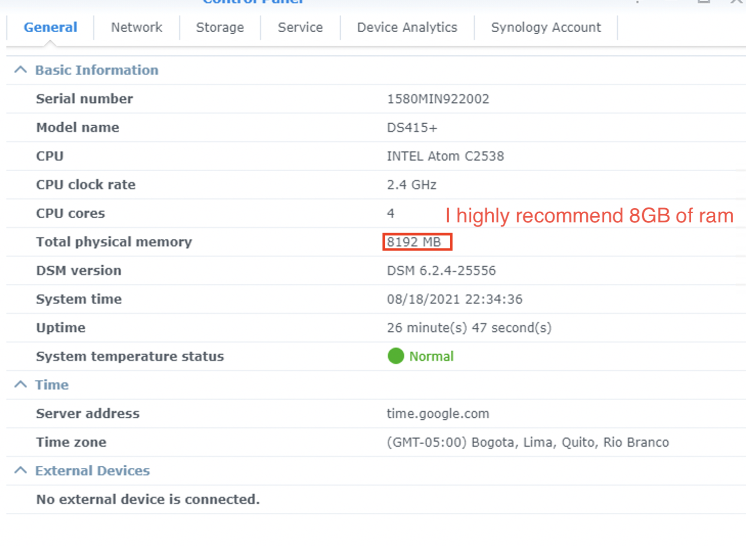
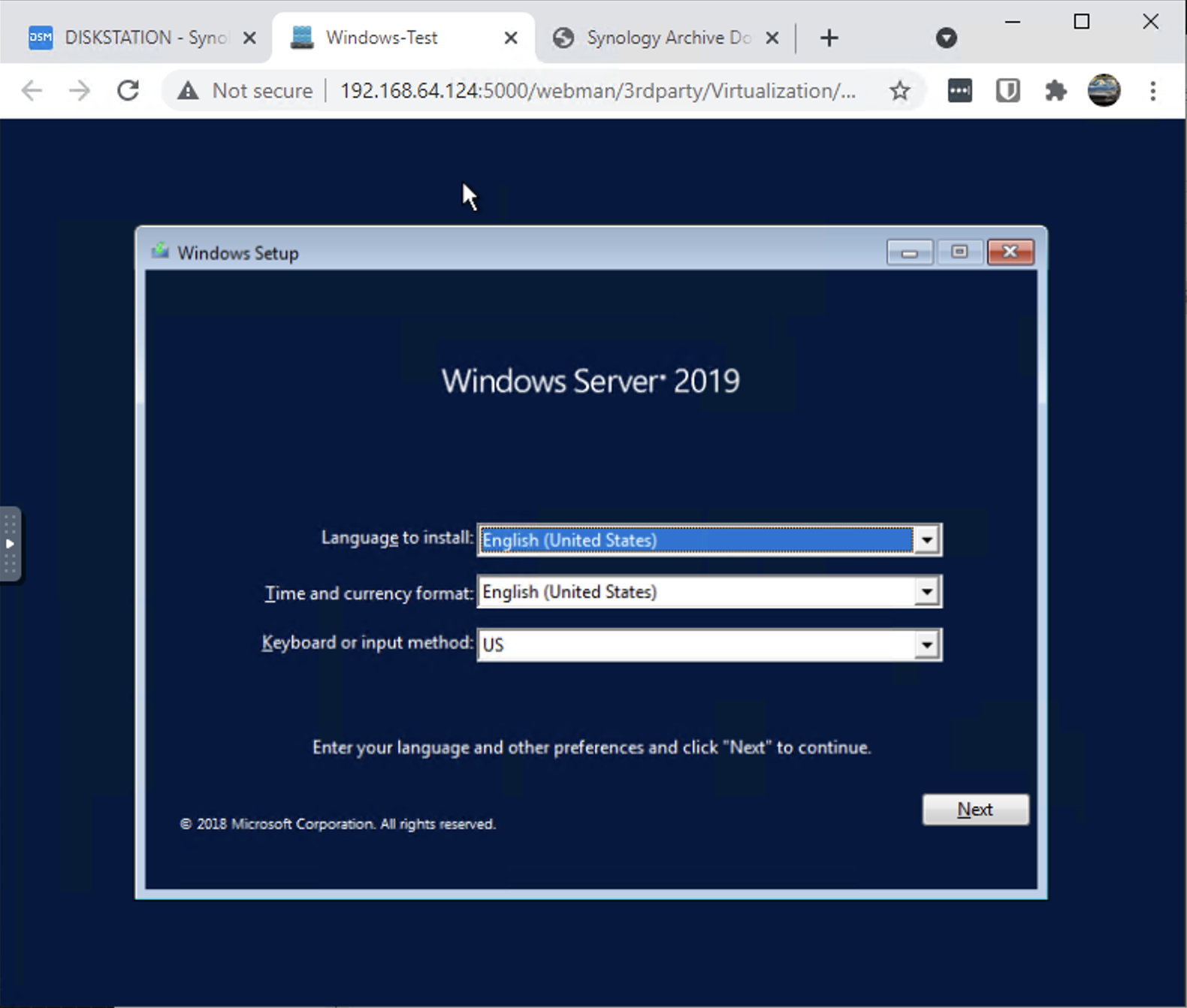
I haven’t seen anyone successfully get VMM working on an upgraded DS415+ with 8GB of RAM.
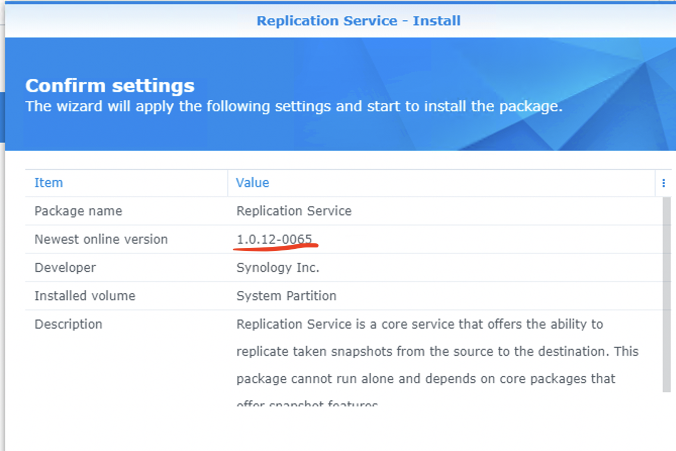
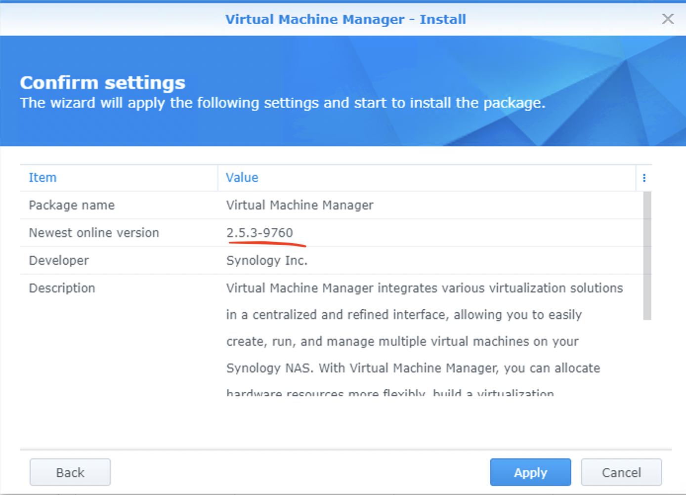
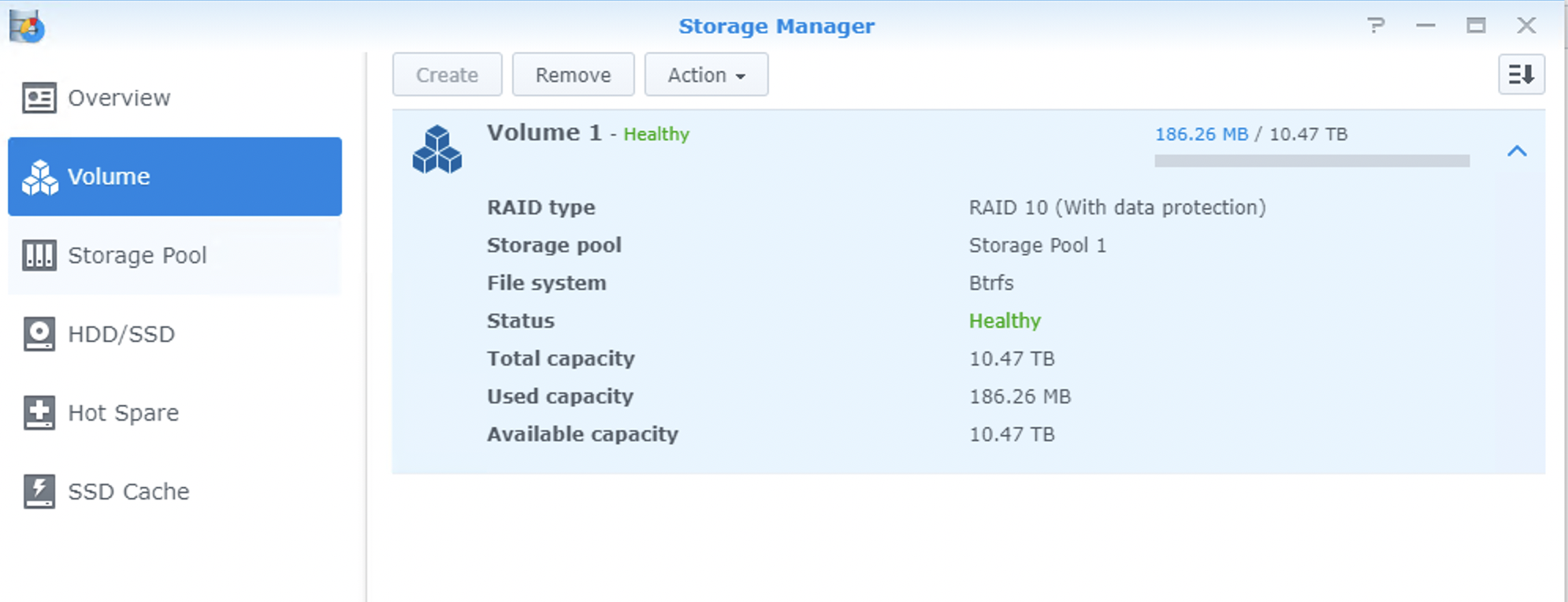
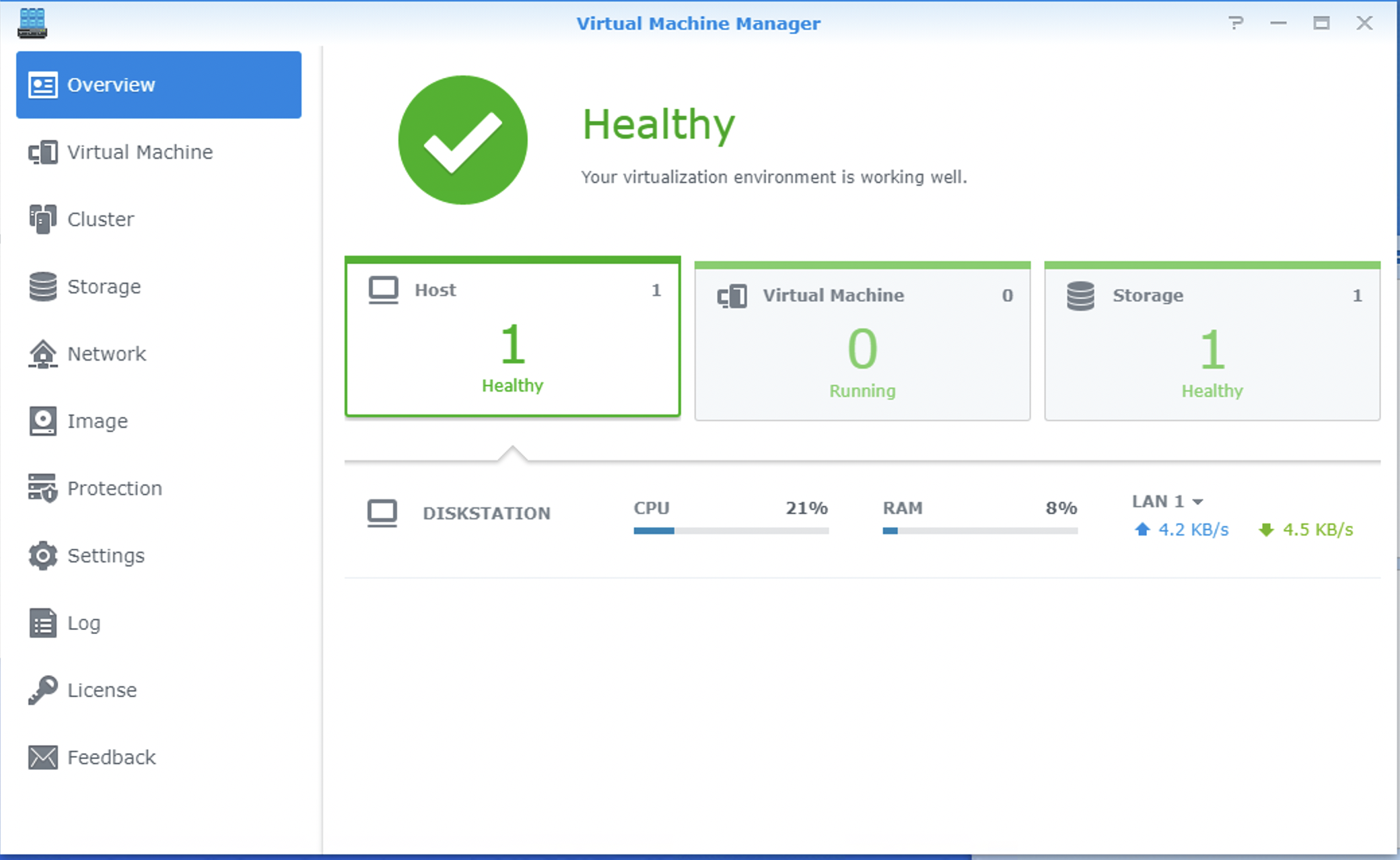
Yes. It IS possible. You have to use specific version of packages found at: https://archive.synology.com/download/Package/
Replication Service: 1.0.12-0065
Virtualization: 2.5.3-9760
I’m running DSM: 6.2.4-25556
Photos below:
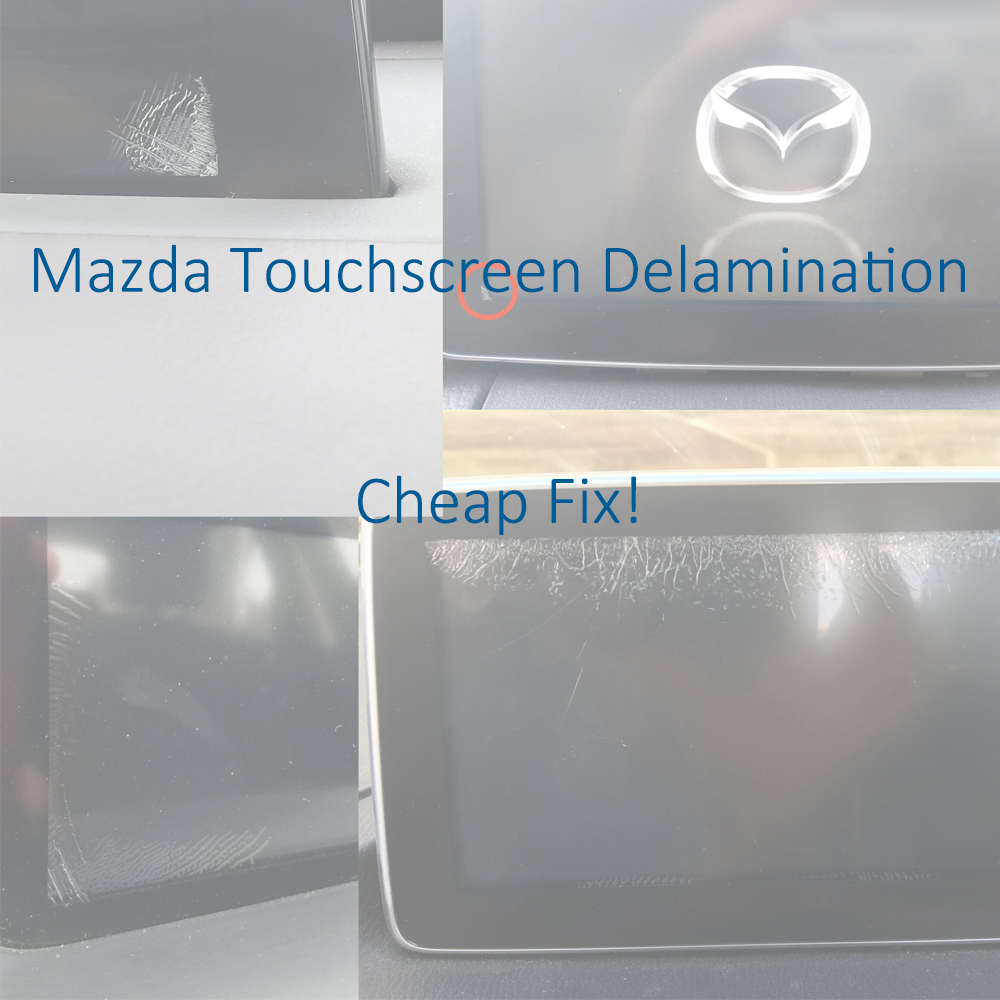
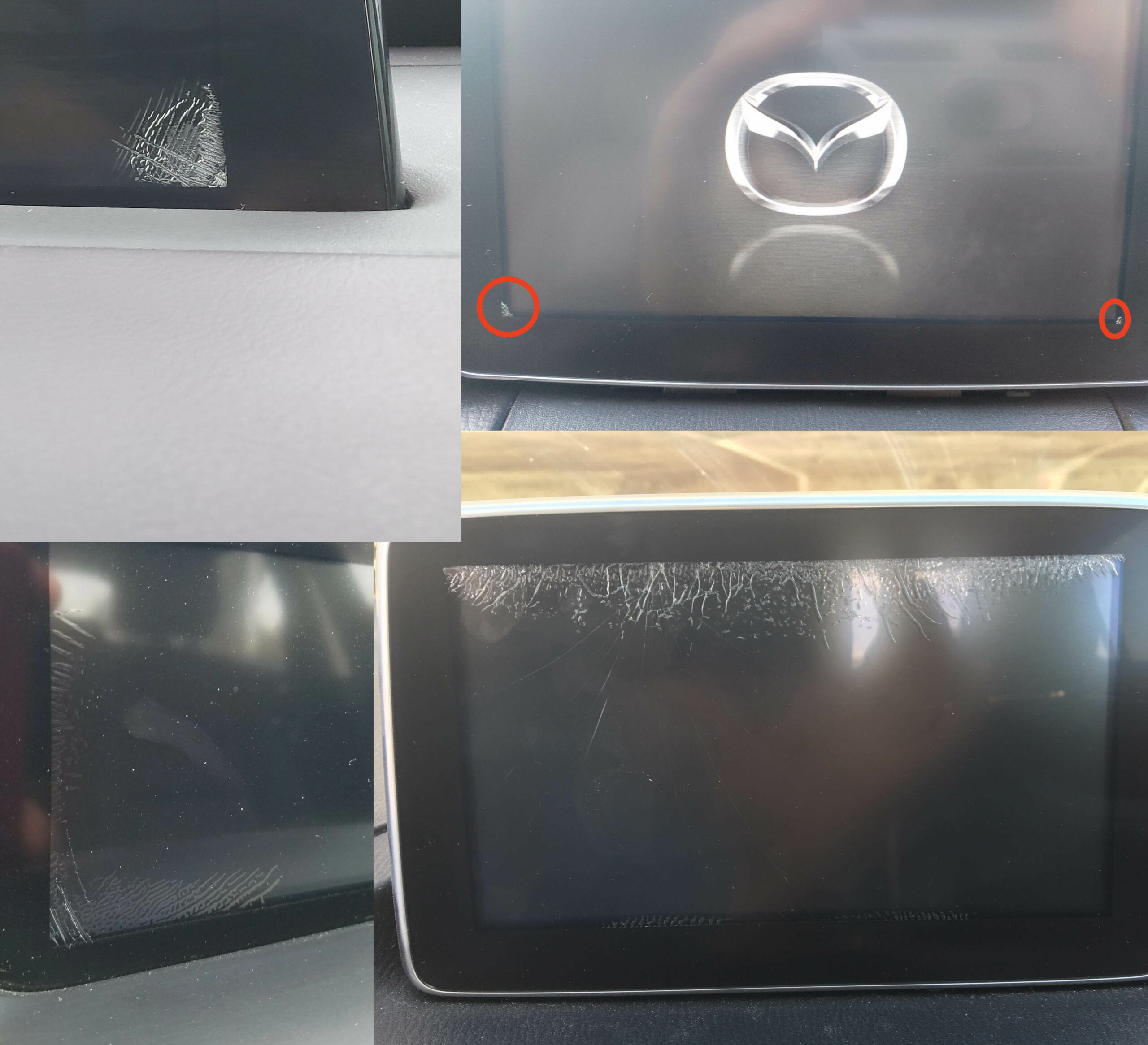
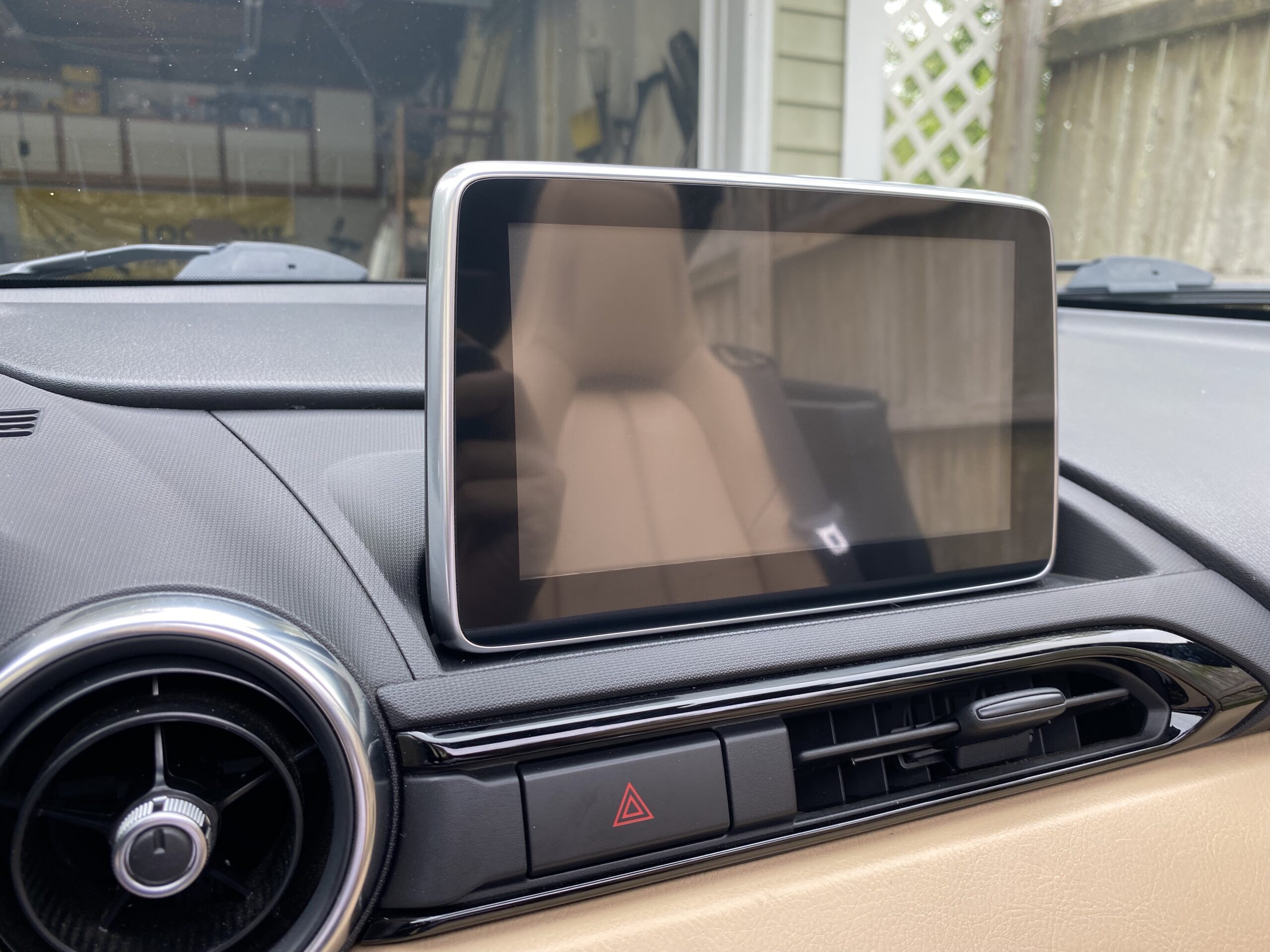
If your Mazda Connect screen has developed cracks, ghost touch issues, or random touchscreen behavior, you may be able to fix it without replacing the entire CMU or screen assembly.
This repair uses basic tools and an inexpensive replacement digitizer, typically around $15–$25, making it far cheaper than a dealership repair or full screen replacement.
This issue is usually caused by adhesive delamination between the touchscreen cover and the digitizer after repeated hot and cold cycles.
If your vehicle is still under full warranty, Mazda may replace the unit at no charge.
View Mazda TSB / warranty information
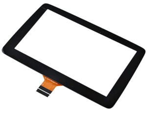
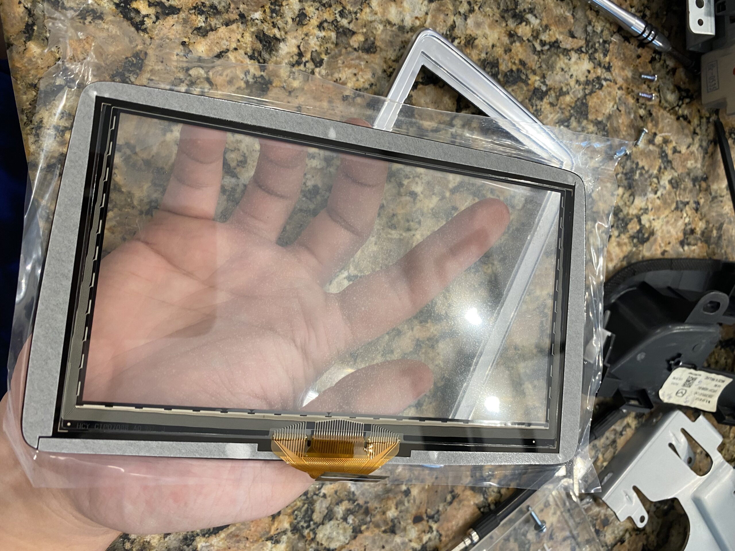
Before ordering parts, verify which touchscreen digitizer your screen uses.
The 36-pin version is typically found on older assemblies, while the 50-pin digitizer is the newer design. Always confirm your connector type before purchasing a replacement.
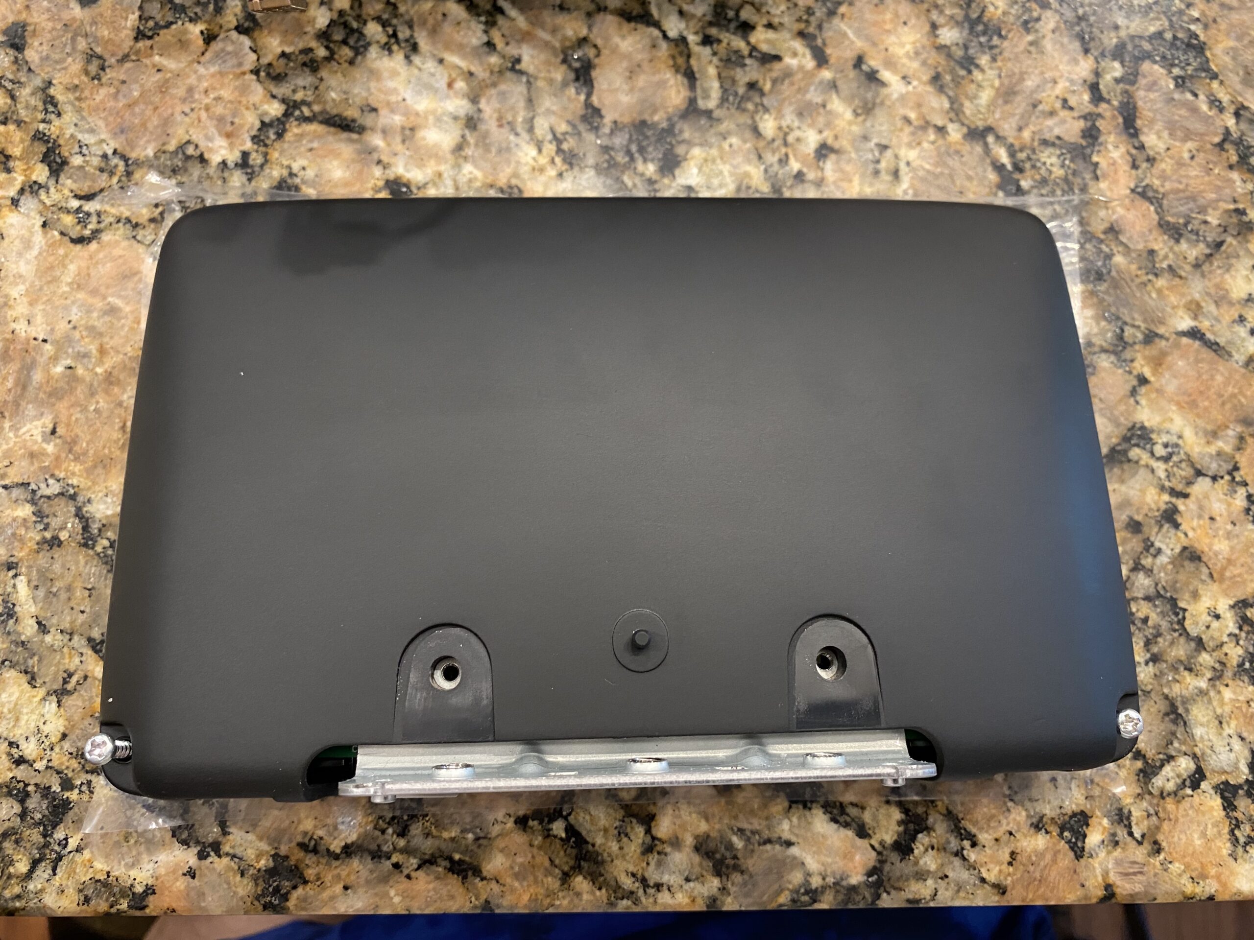
It is said that 2018+ models with the black bezel trim (instead of chrome) feature the newer 50 pin digitizer. If someone can confirm this, and post a comment, that would be extremely helpful.
Note 2: None of this applies to the ND3 (2024+) This is a completely different screen, and so far no reports of digitizer de-lamination.
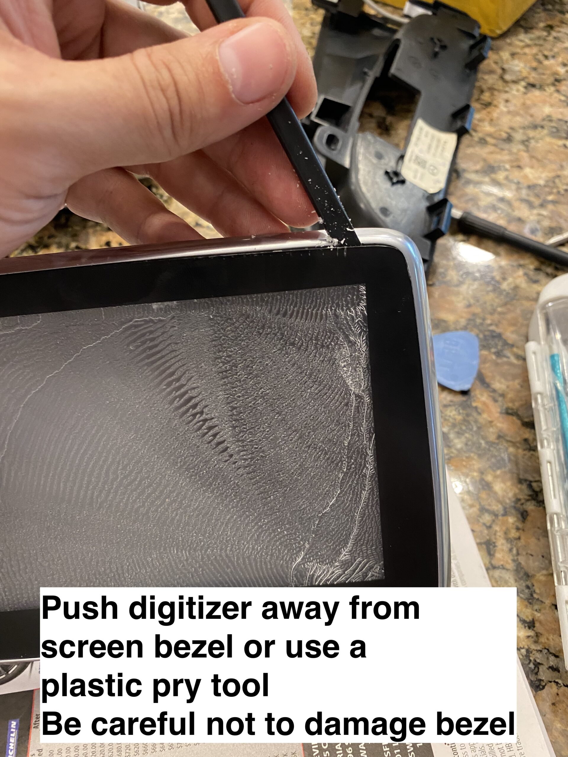
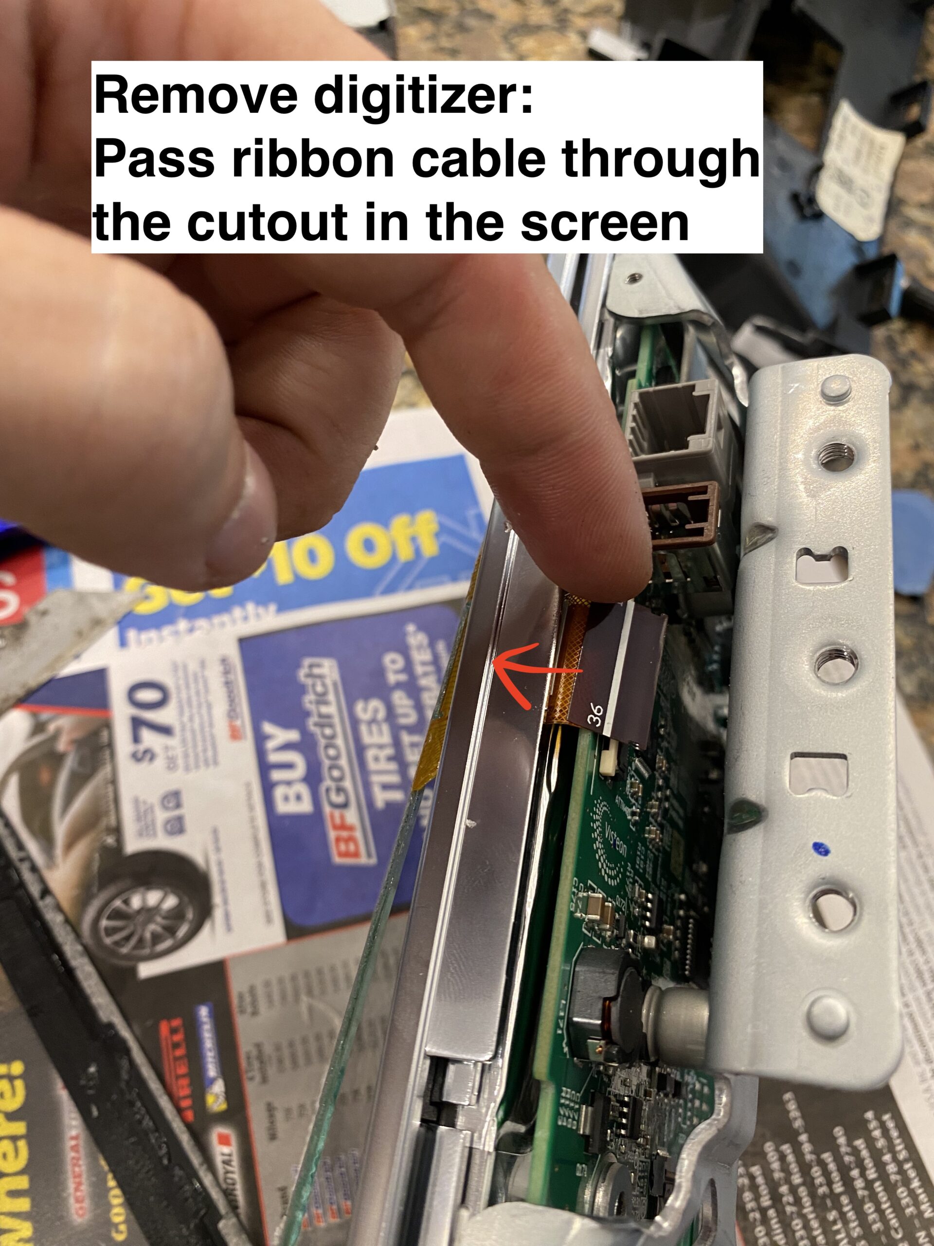
Use caution: parts of this repair require careful handling to avoid damaging the screen PCB or ribbon cables. If you are not comfortable working on delicate electronics, this may not be the right DIY project for you.
These photos were taken during reassembly after the screen was repaired, so some images may show the unit going back together rather than coming apart.
If this guide helps you, consider using the affiliate links below to purchase the needed parts.
Buy 36 pin replacement touchscreen on eBay (Affiliate Link)
Buy 36 pin replacement touchscreen on Amazon (Affiliate Link)
Buy 50 pin replacement touchscreen on eBay (Affiliate Link)
Buy 50 pin replacement touchscreen on Amazon (Affiliate Link)
Disclosure: When you click certain links on this site and make a purchase, this site may earn a commission through affiliate programs, including the eBay Partner Network and Amazon affiliate links.
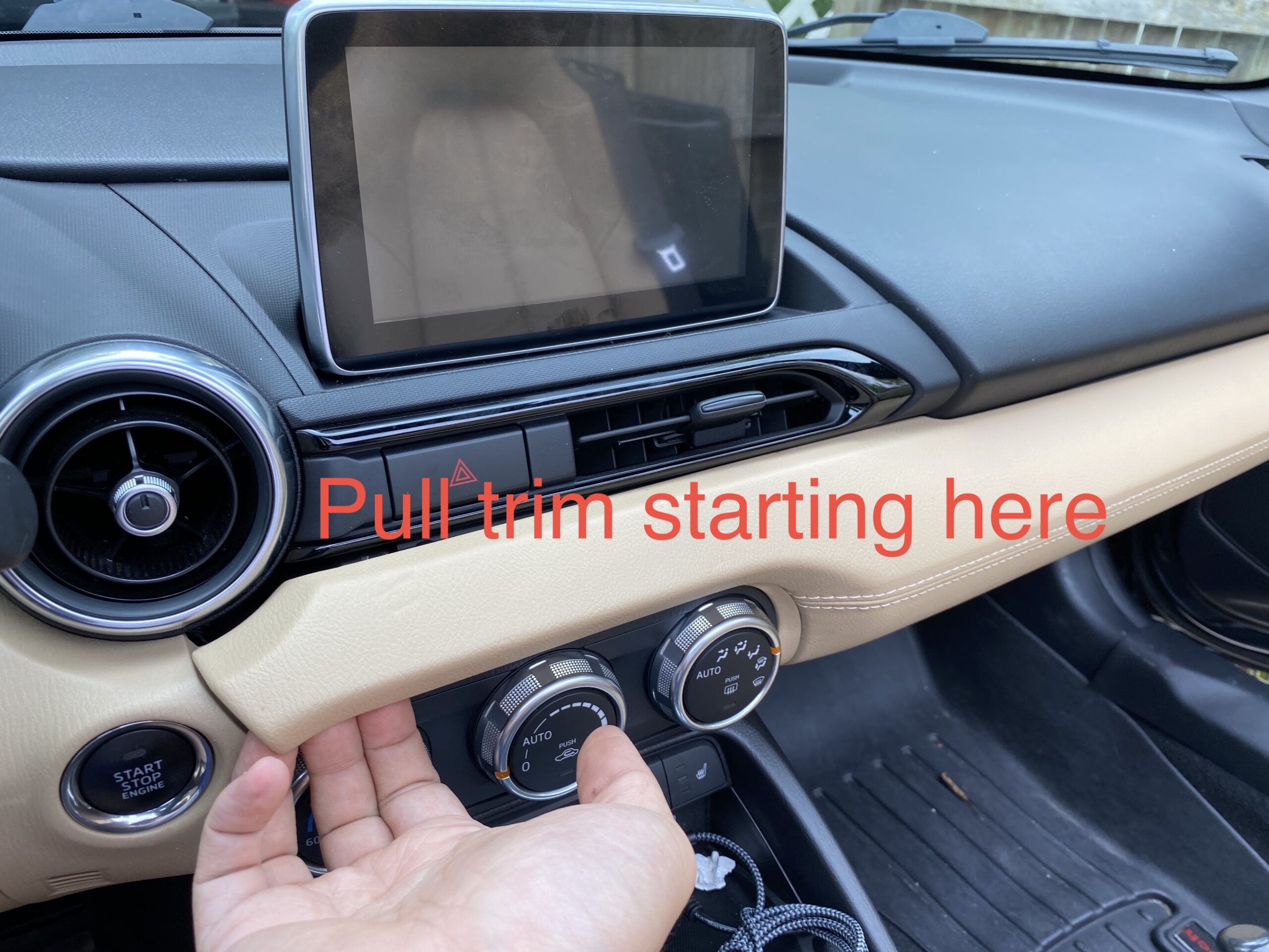
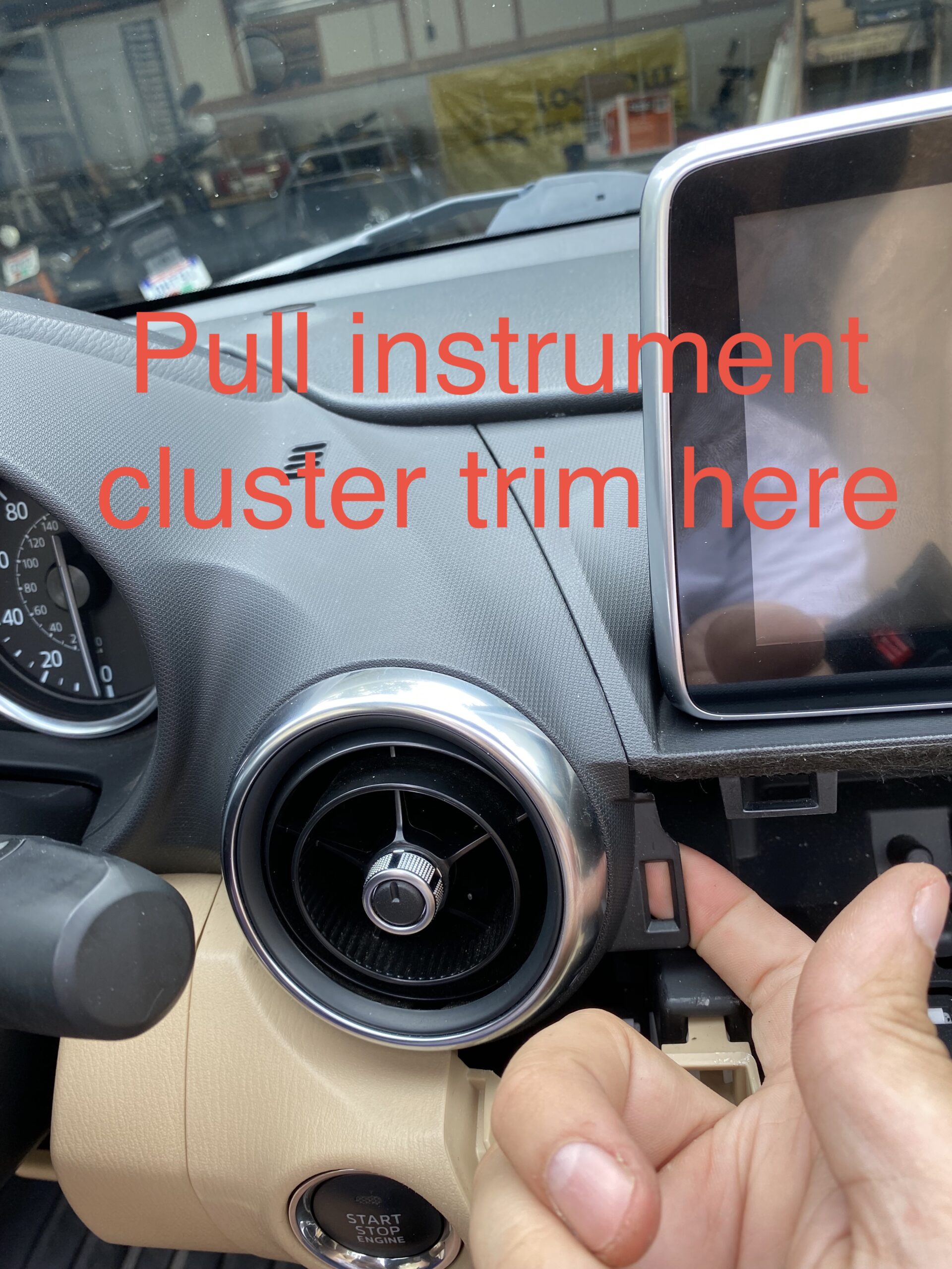
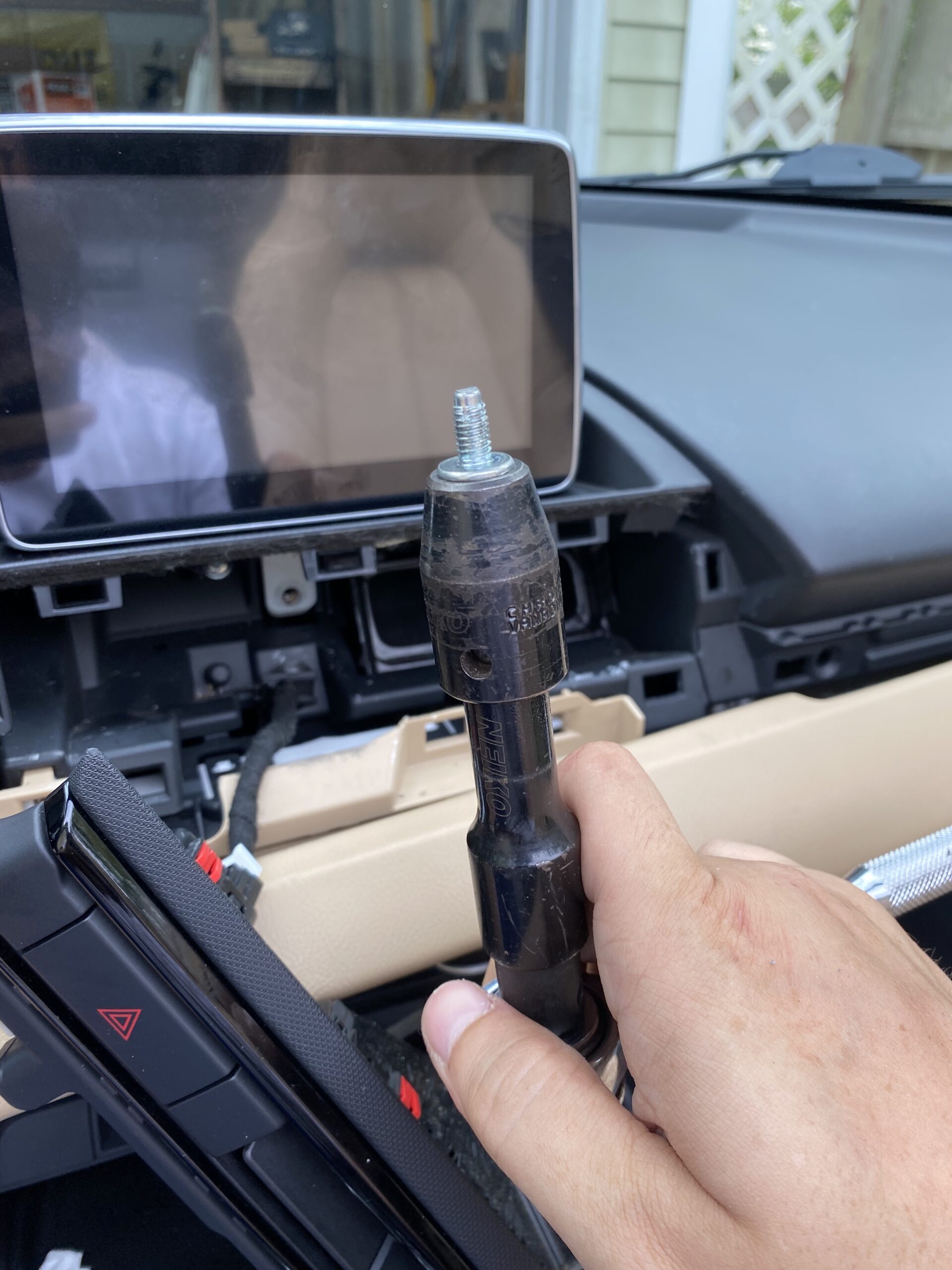
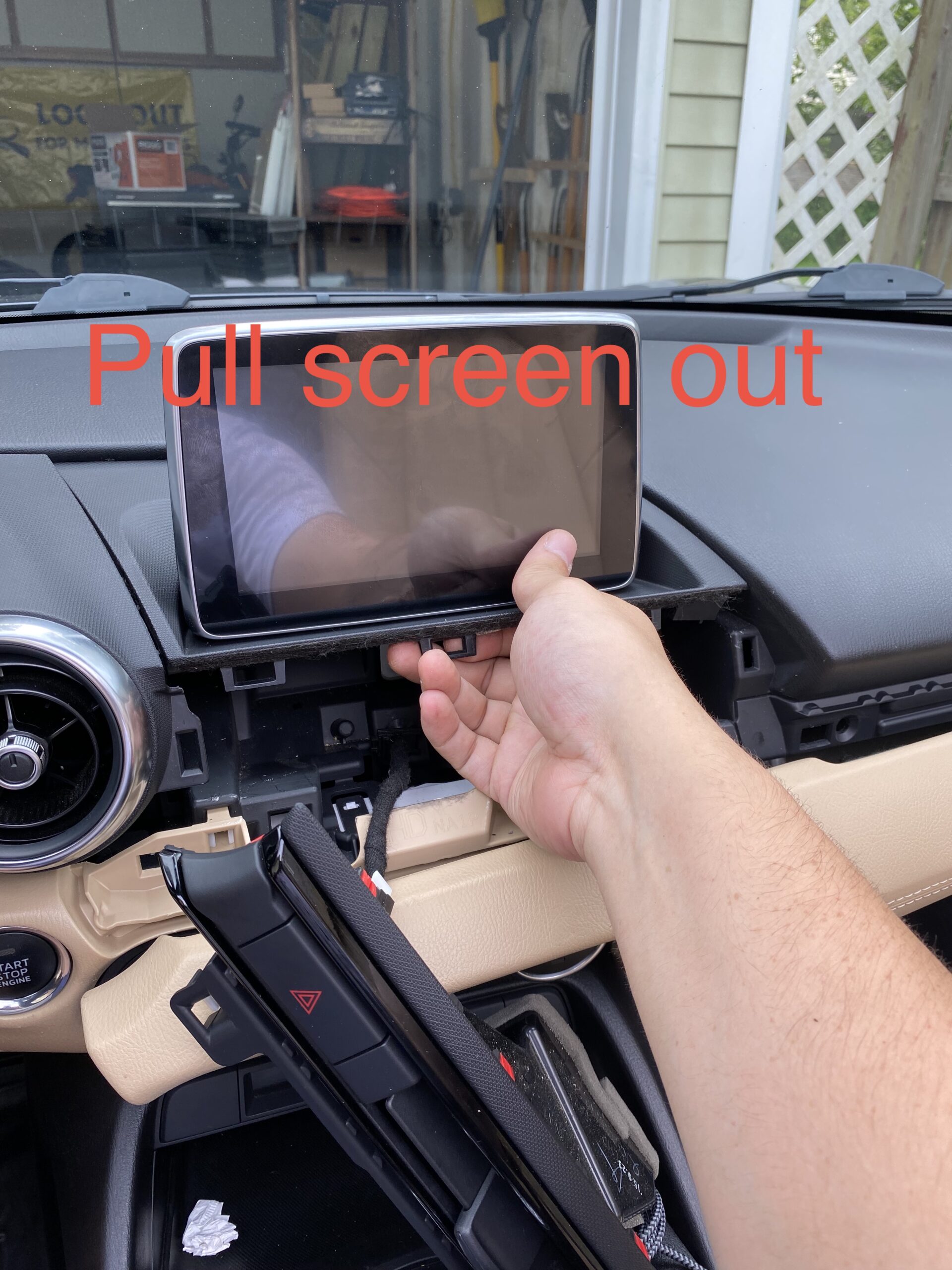
Follow the repair in stages instead of scrolling through one long wall of photos.
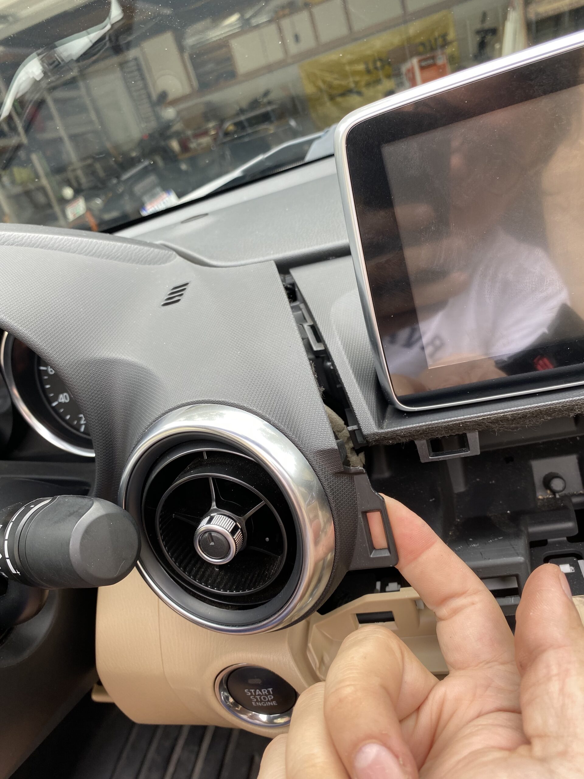
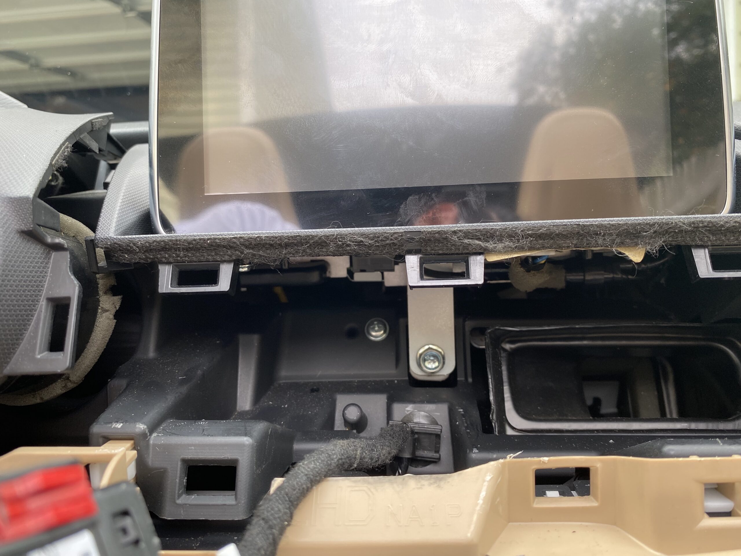
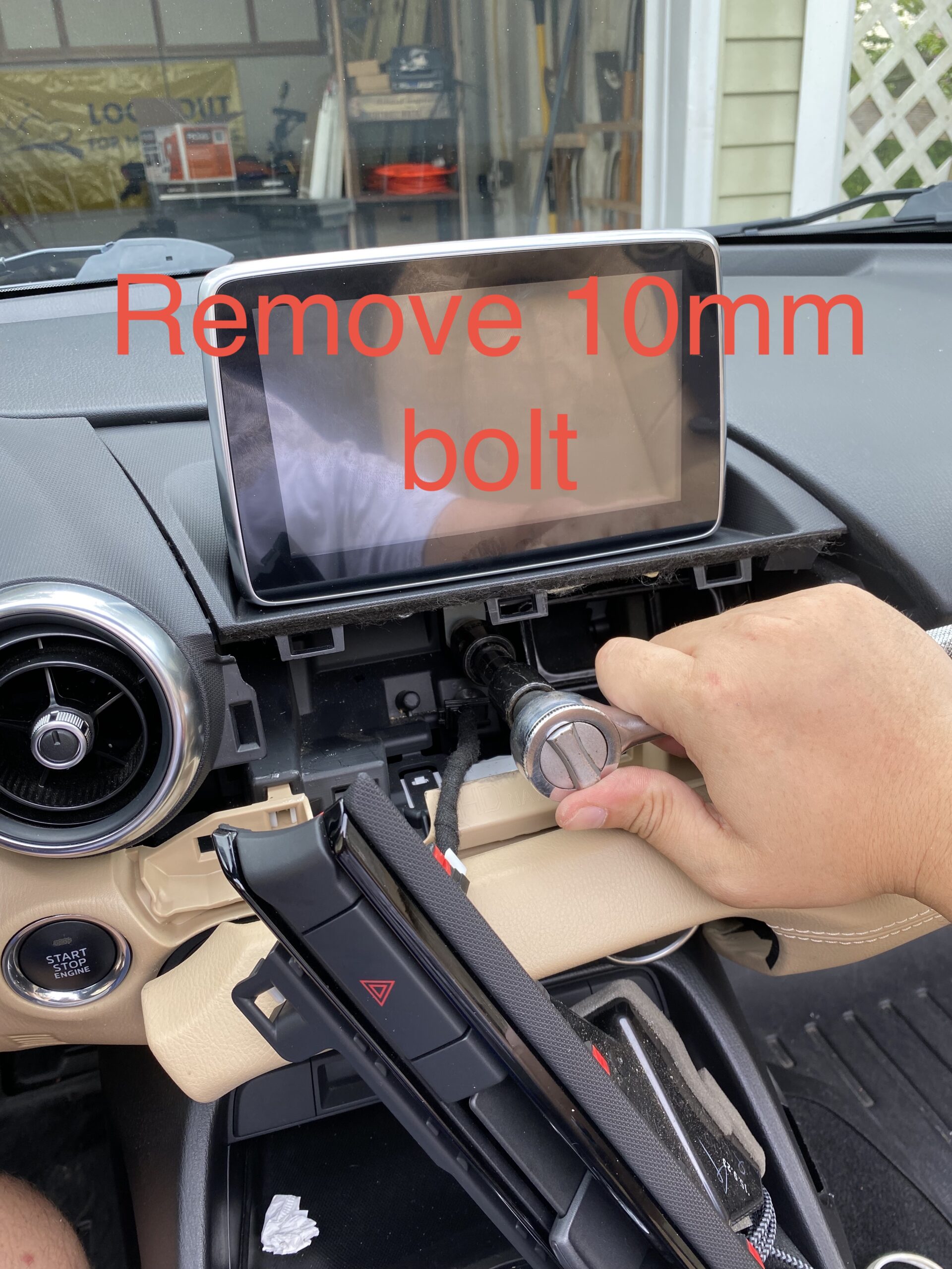
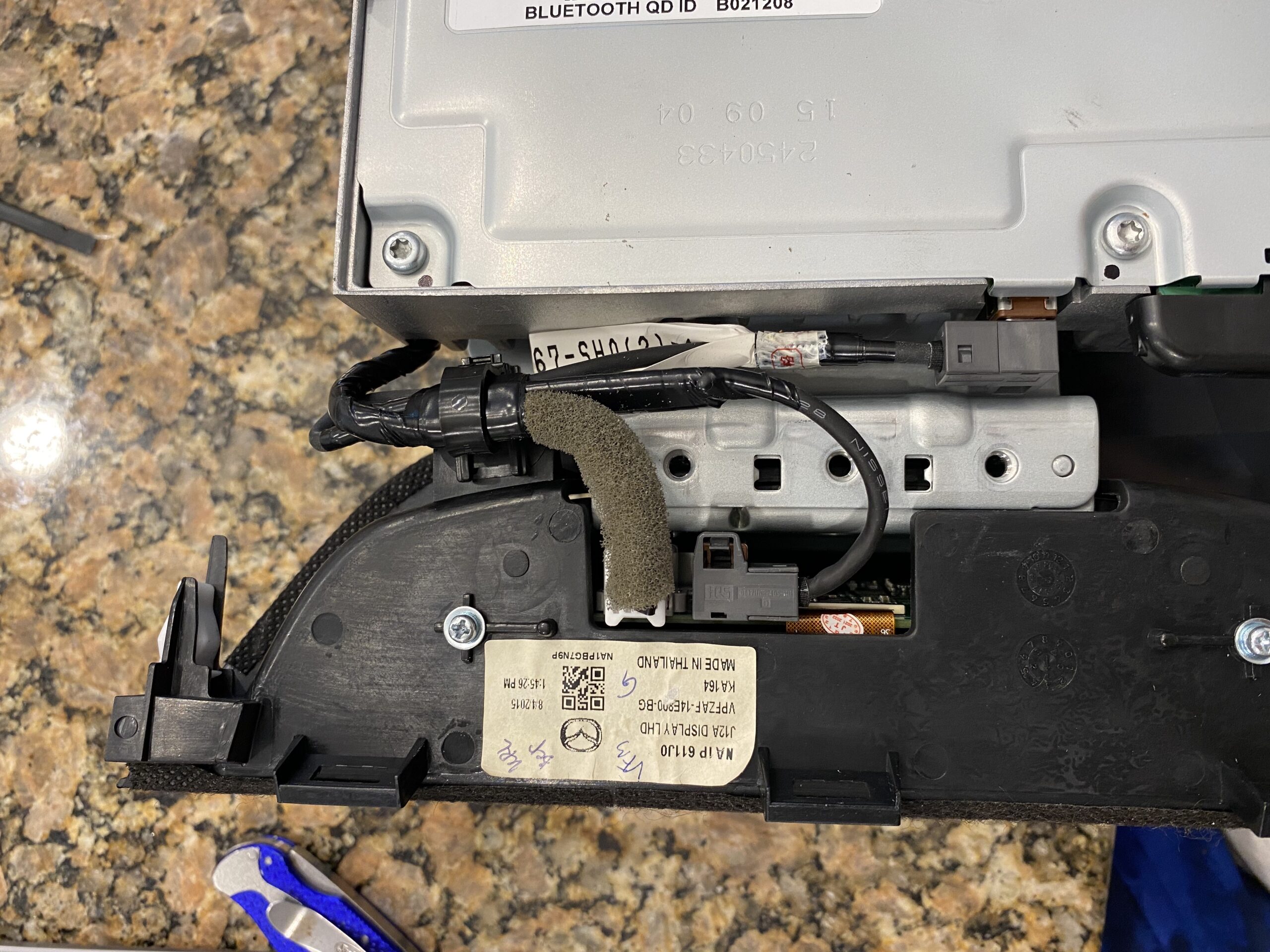
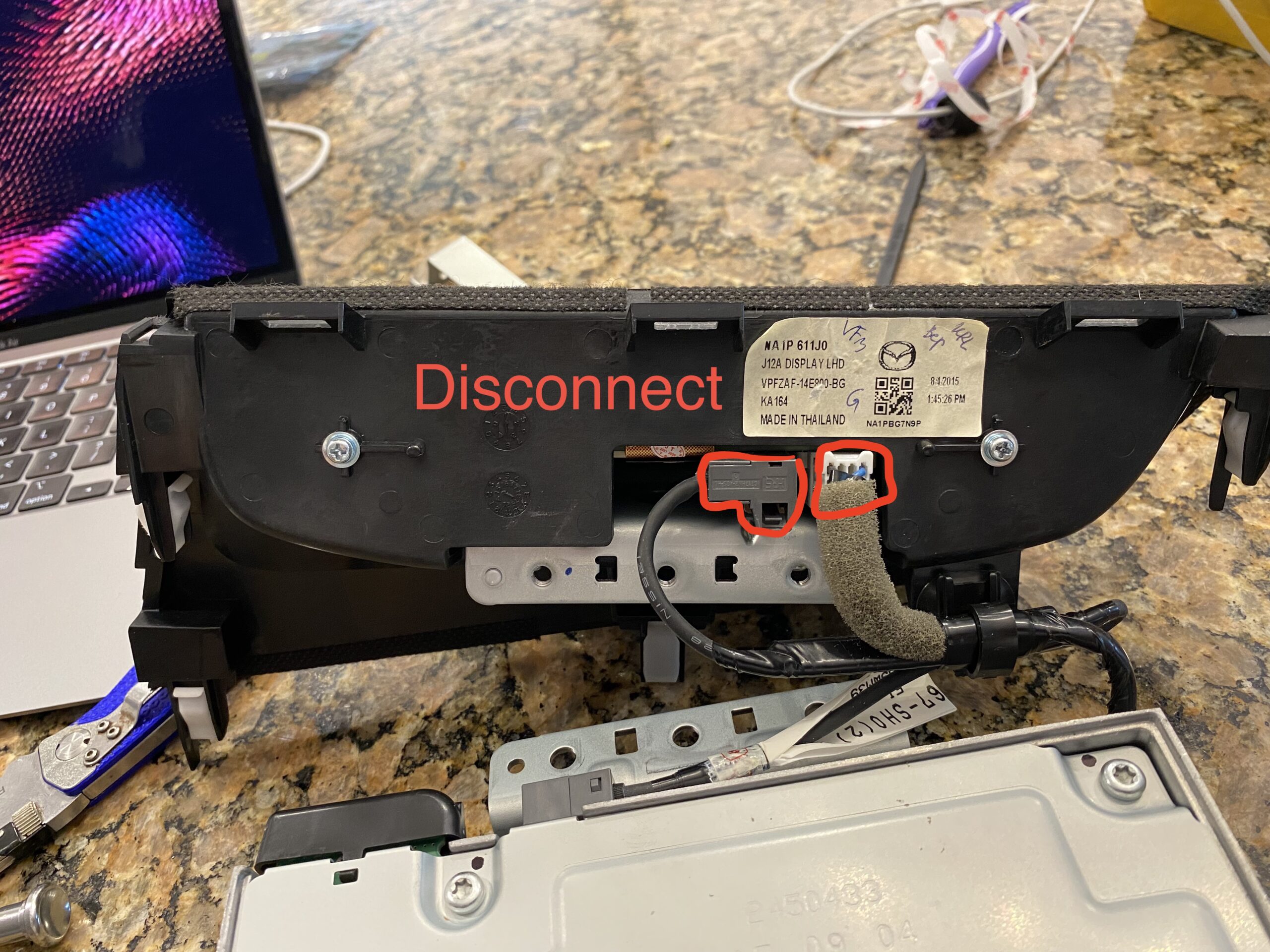
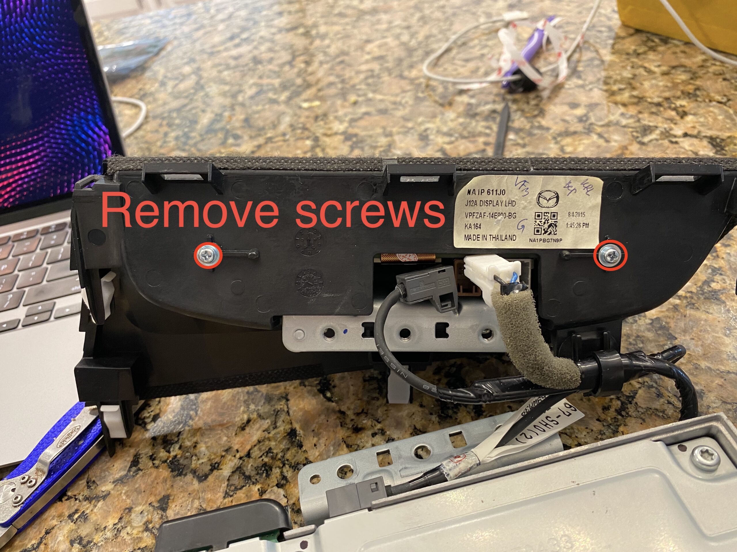
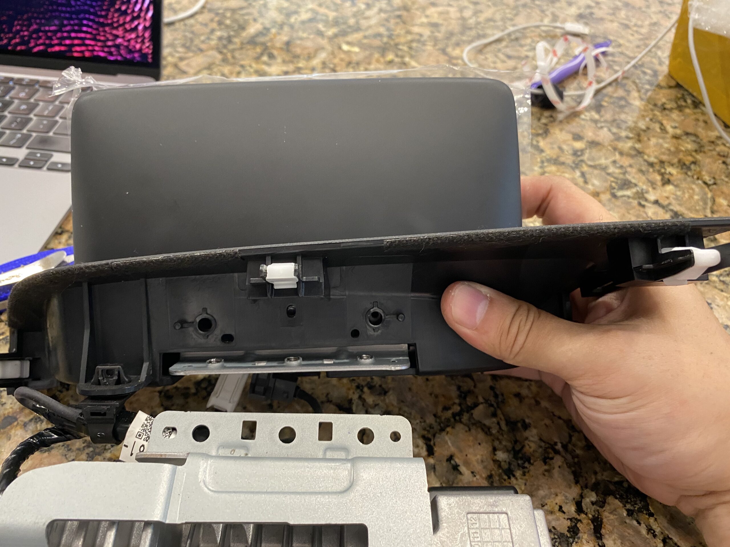
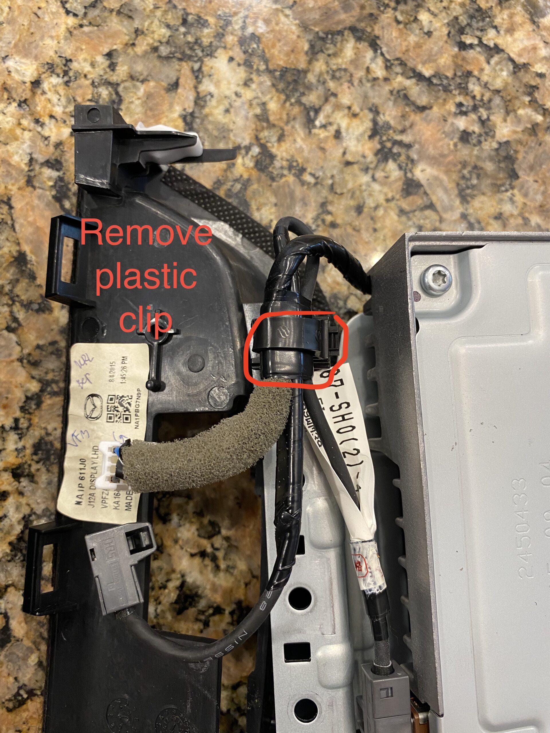
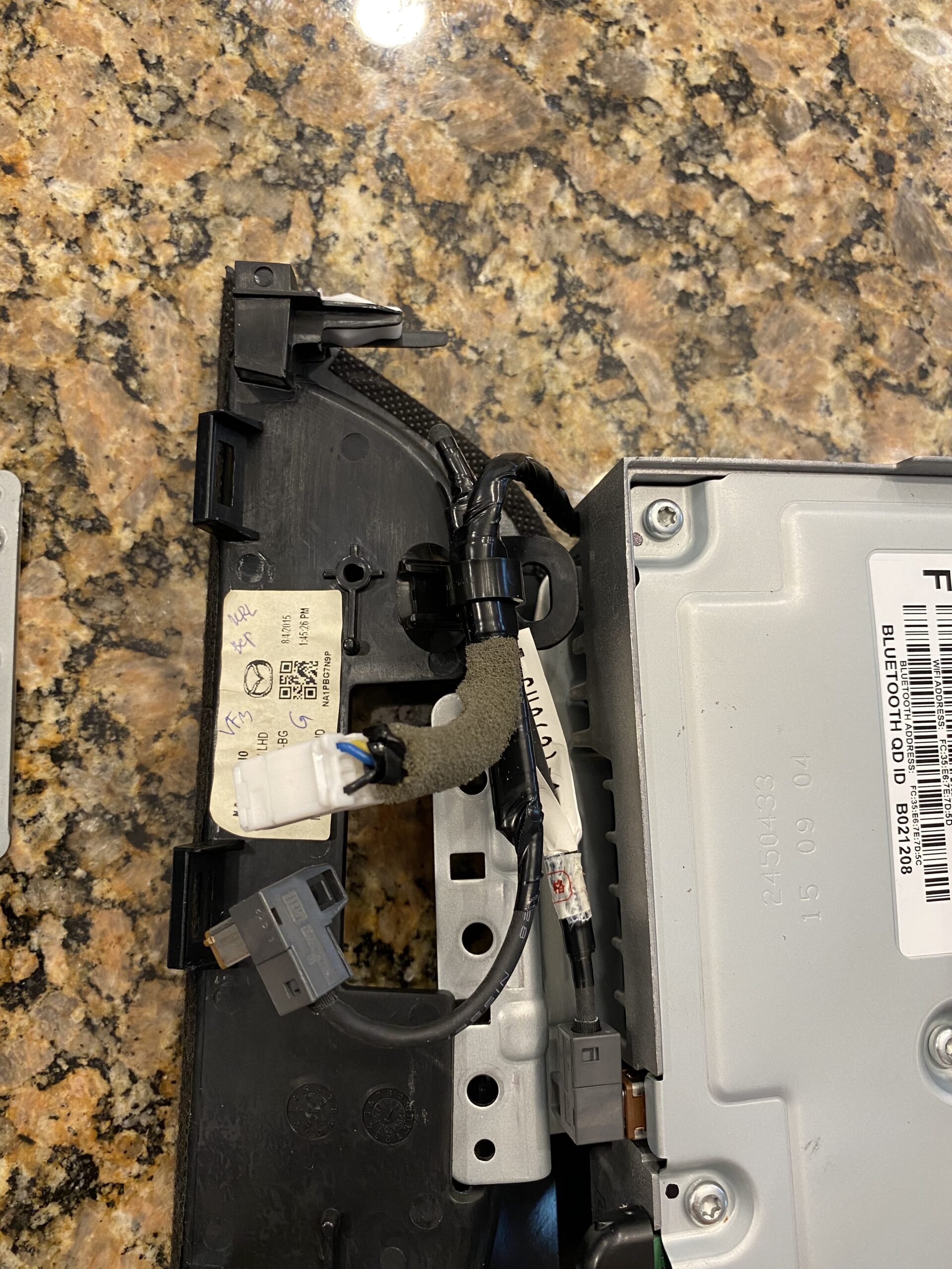
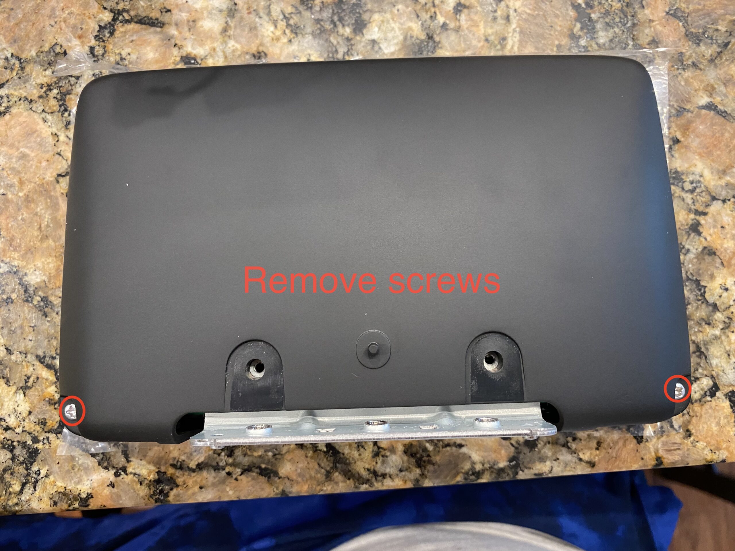
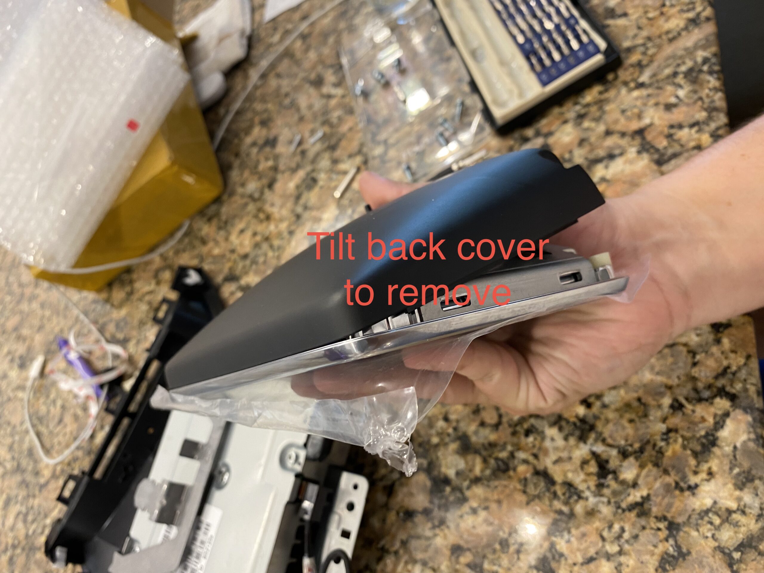
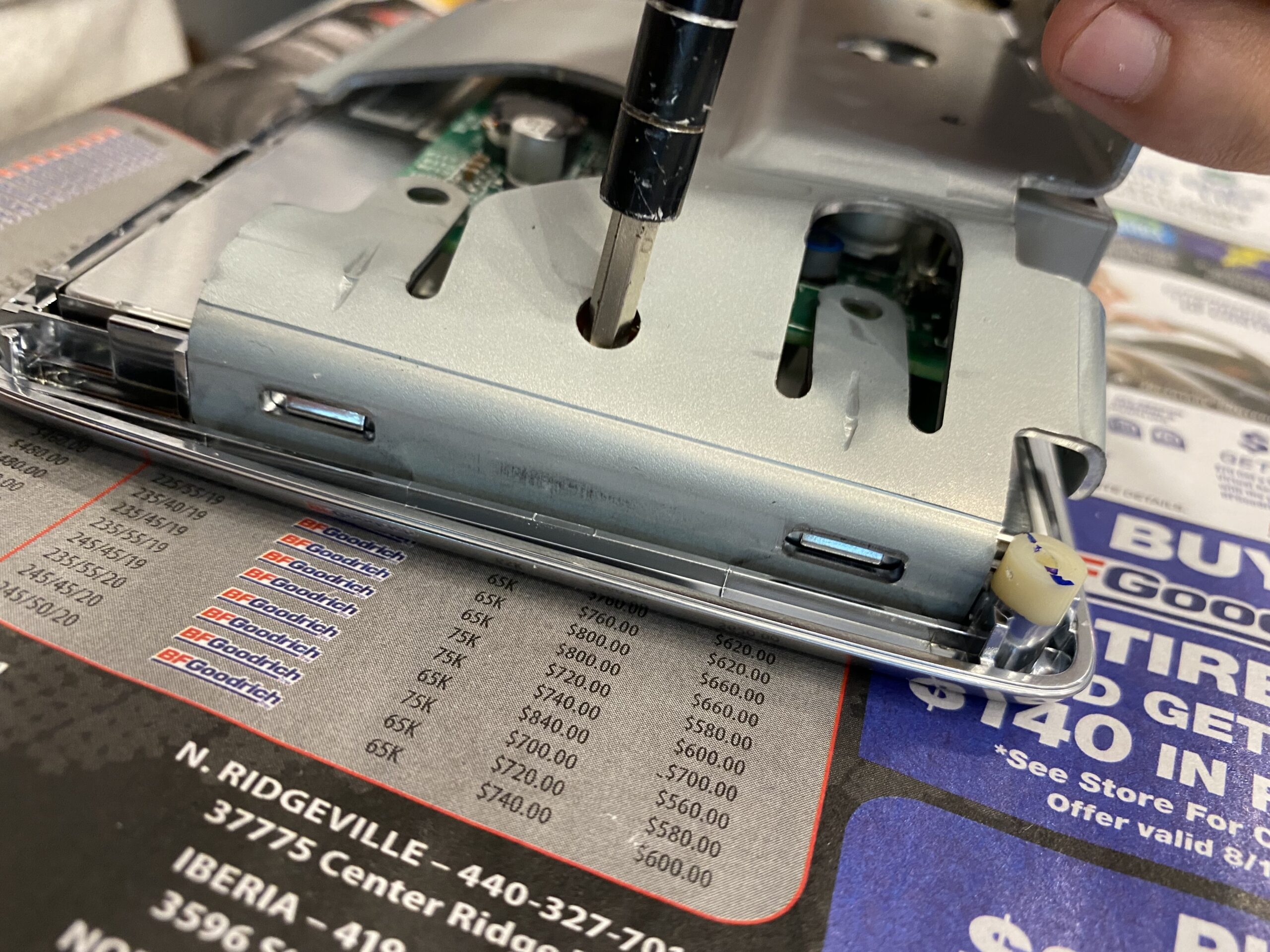
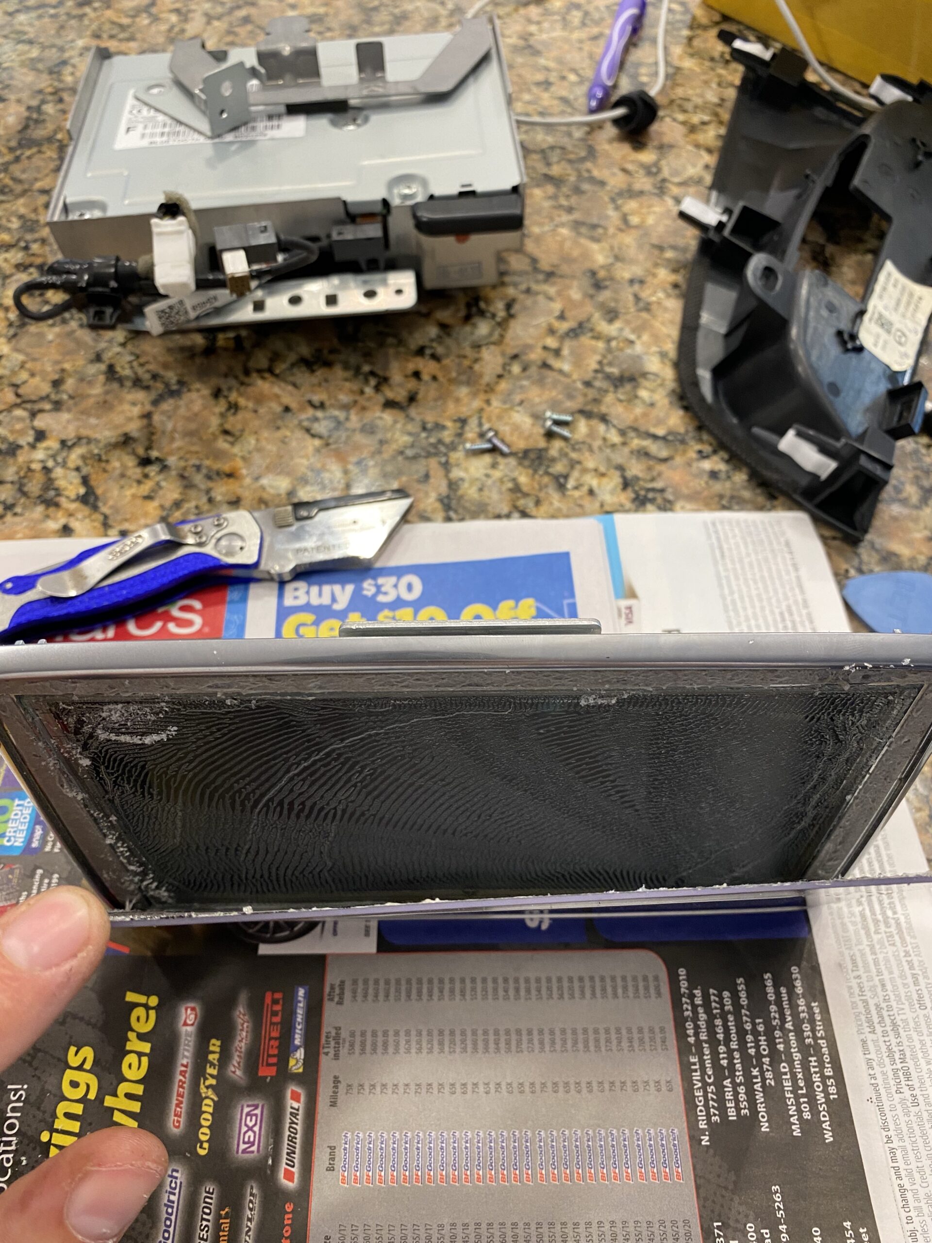
Start by removing the trim pieces and screen assembly carefully. Keep track of screws and clips as you go.
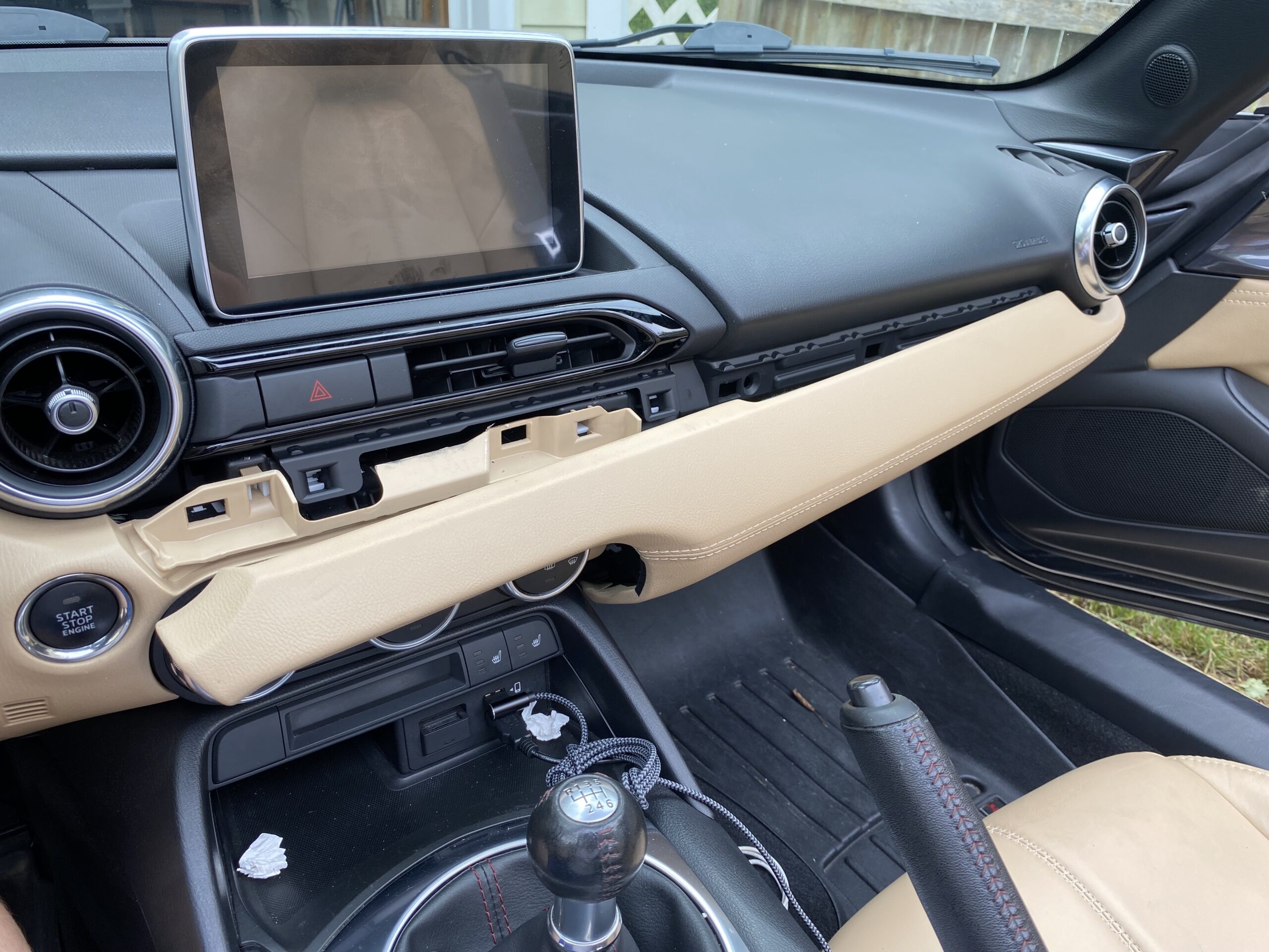
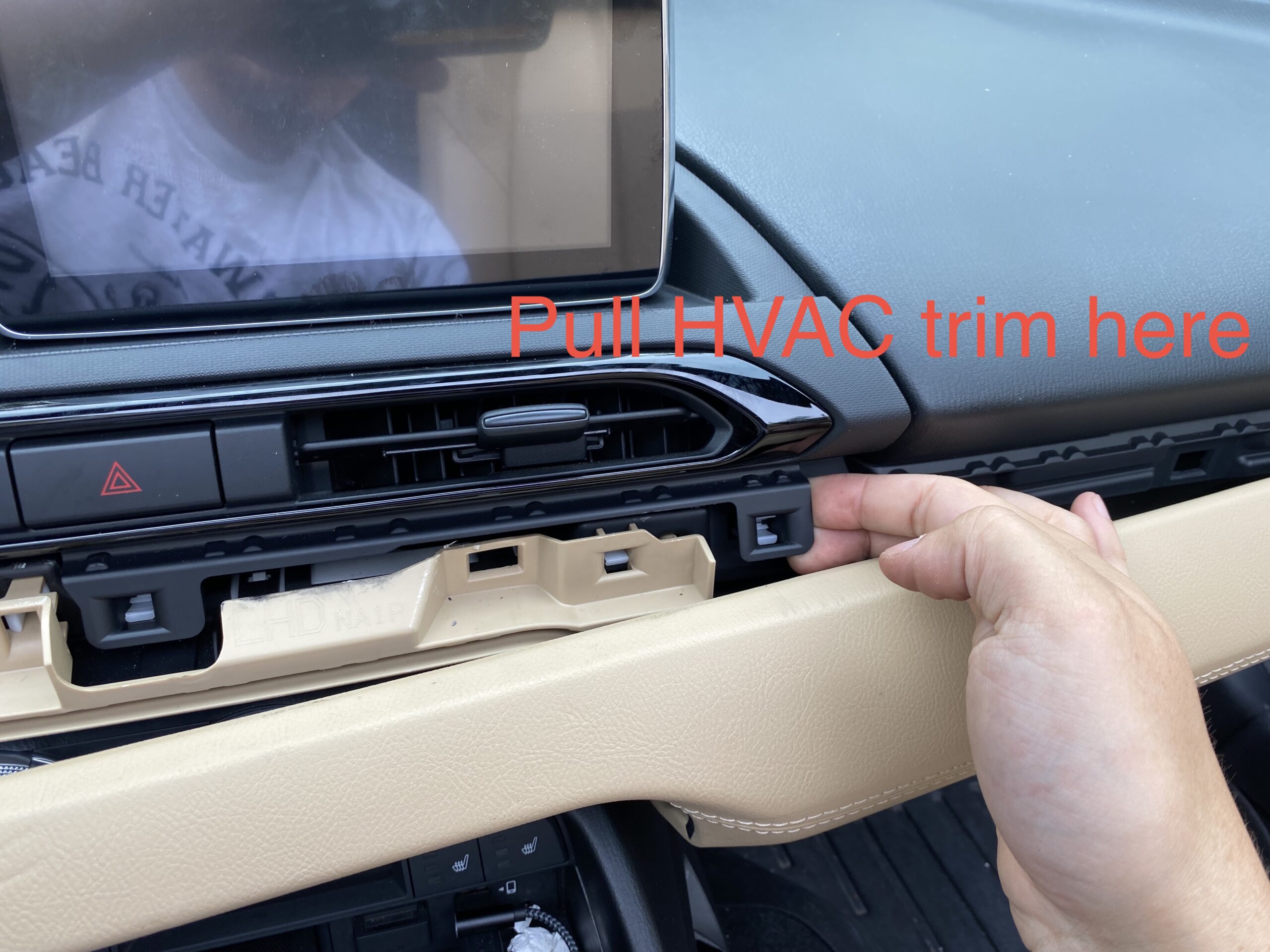
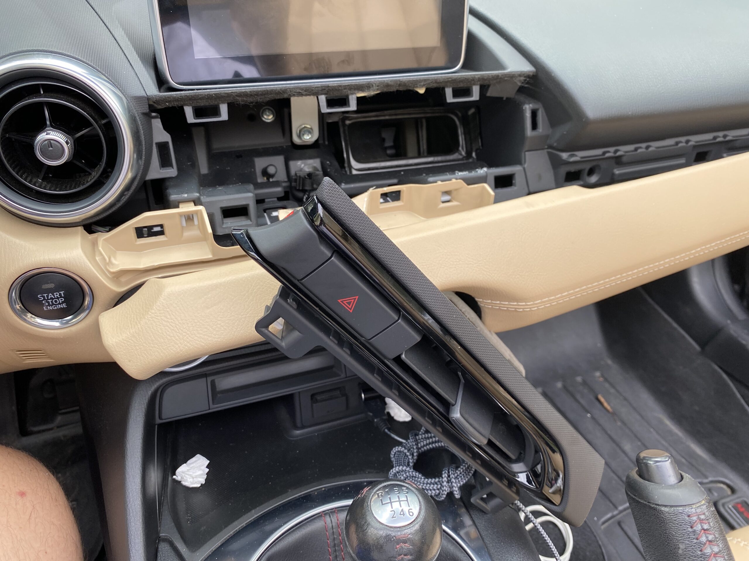
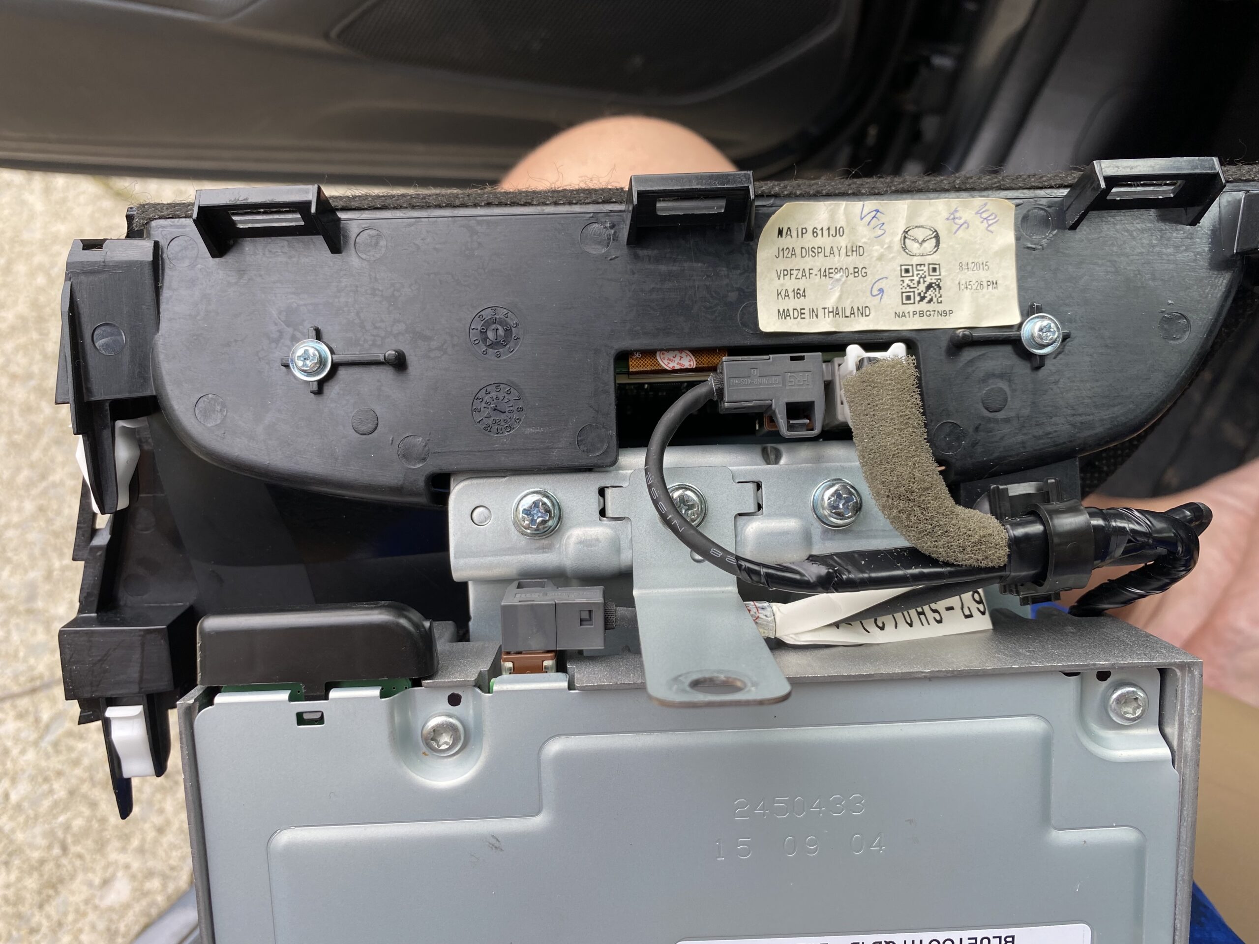
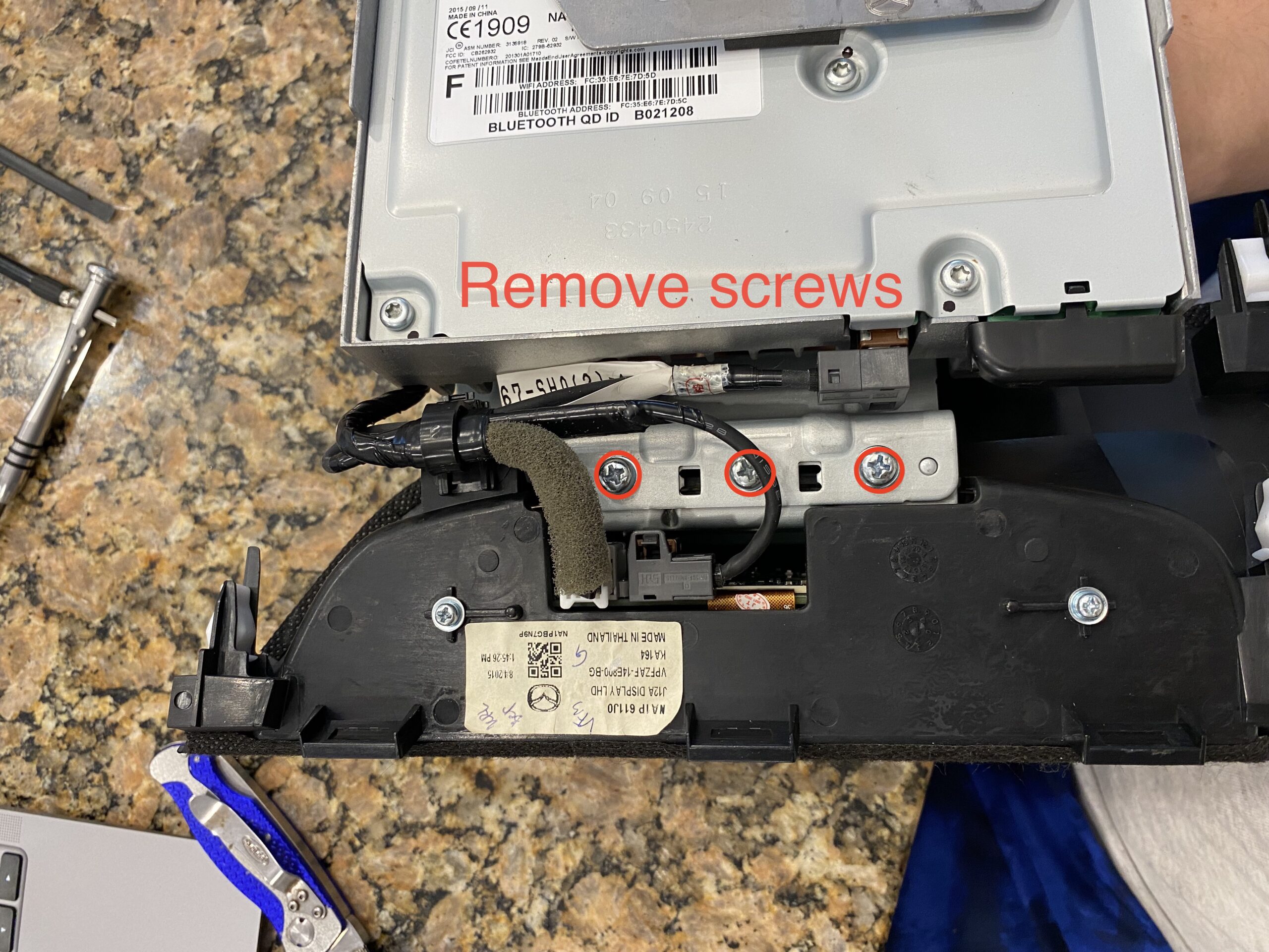
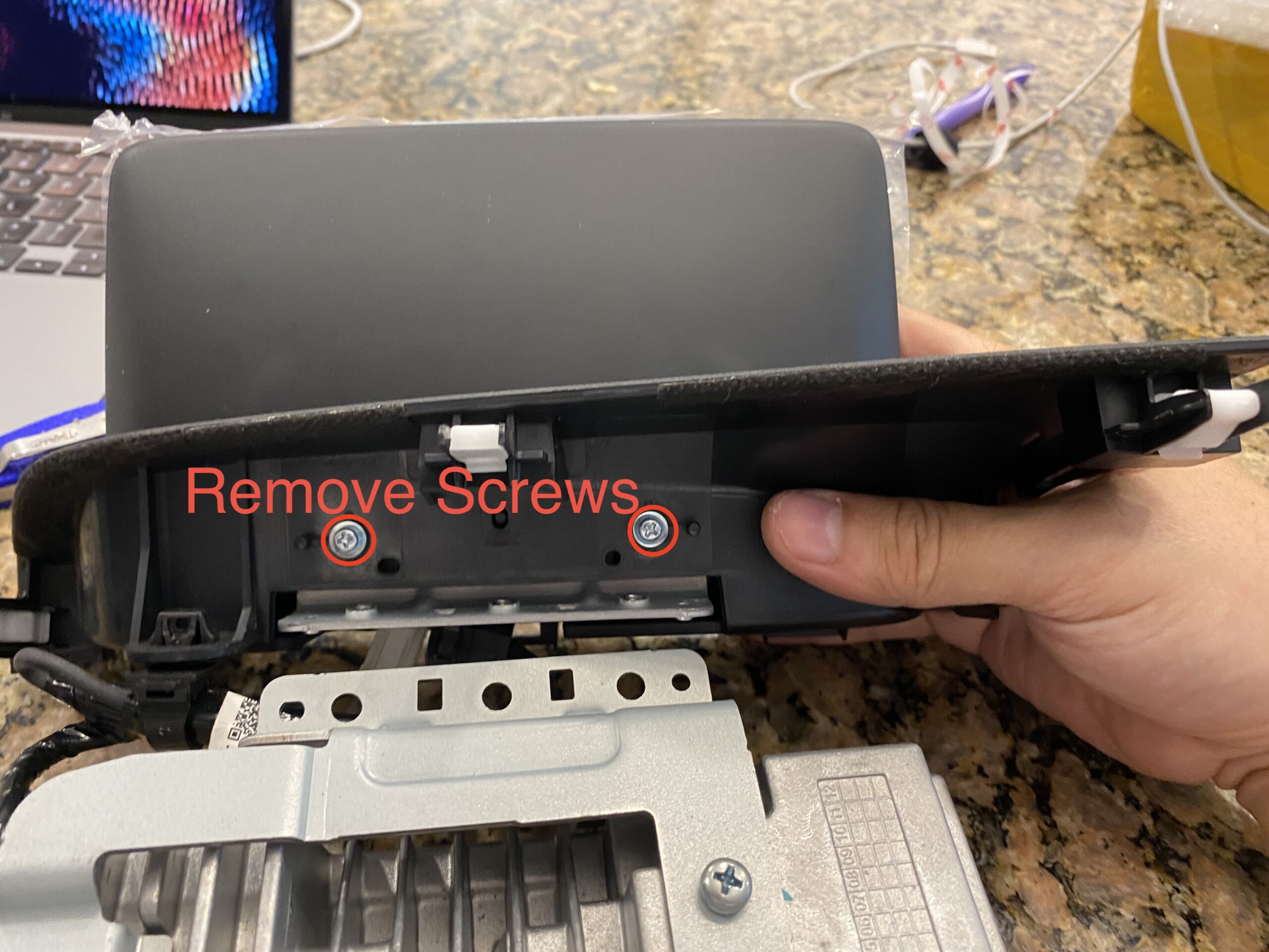
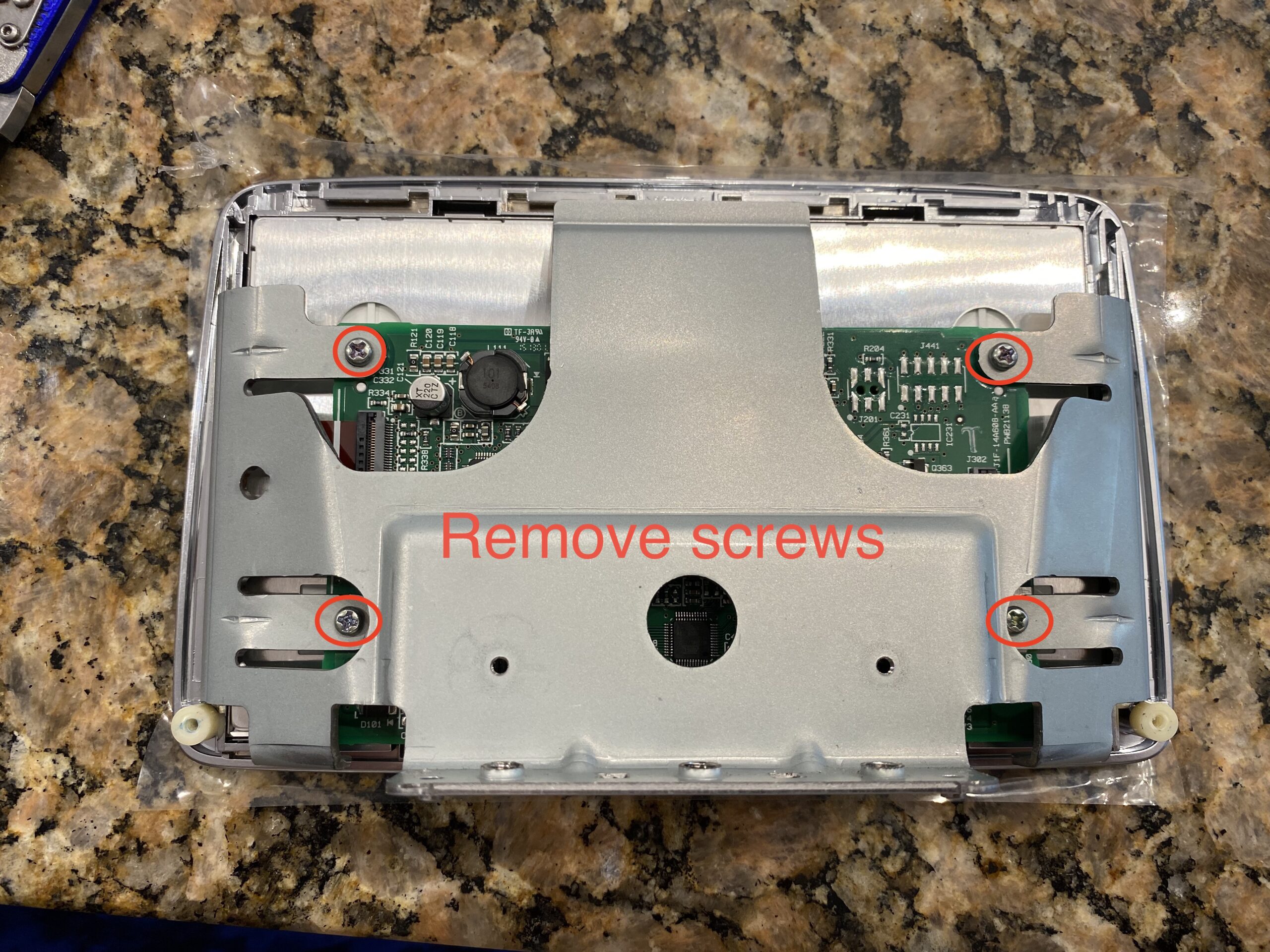
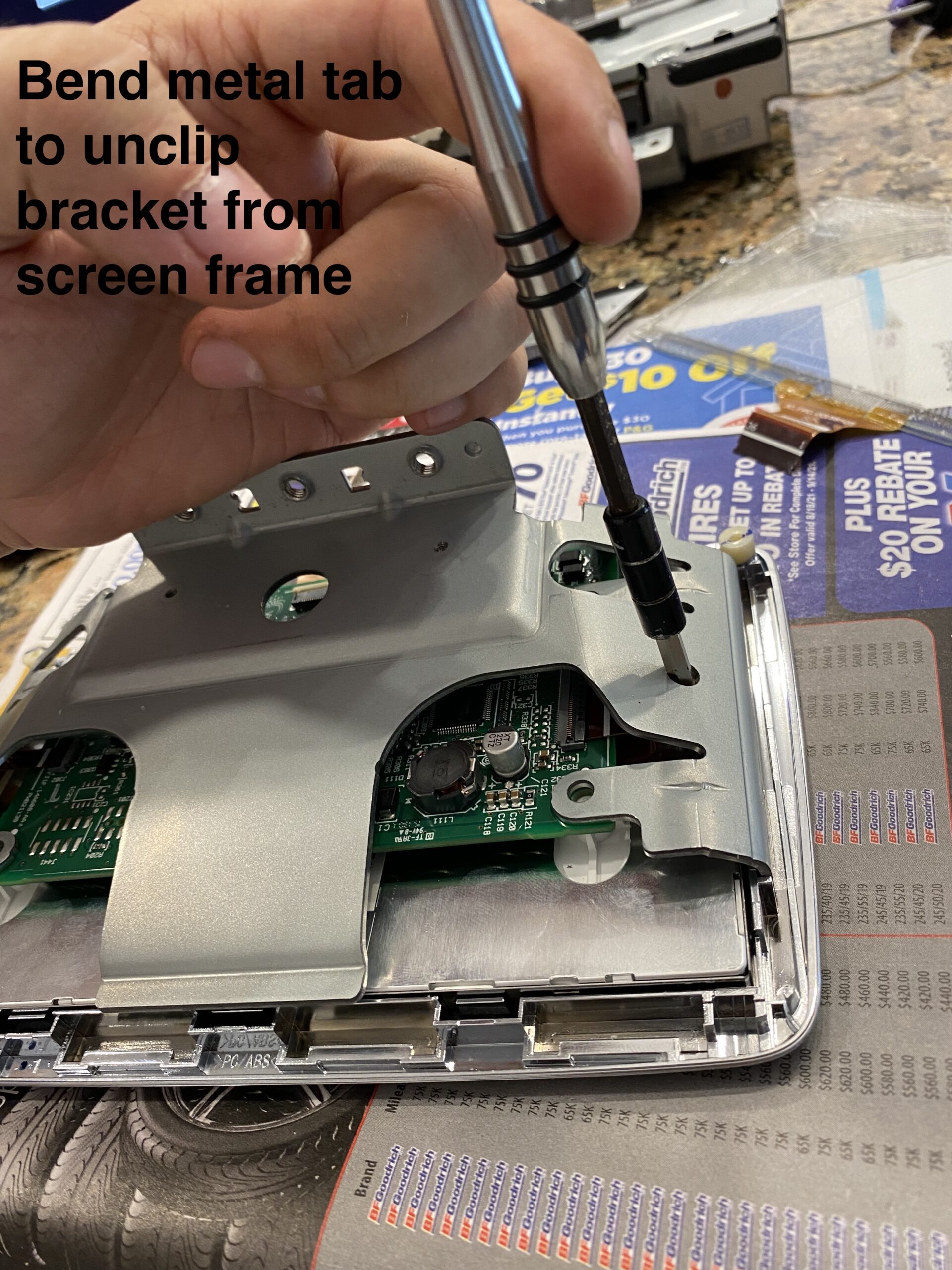
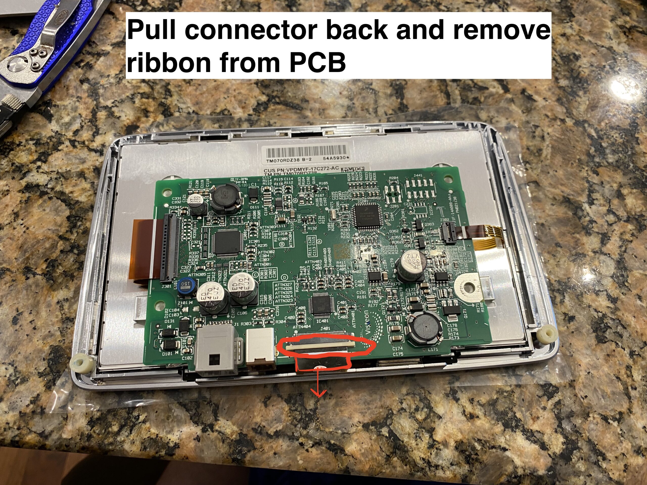
Separate the housing and expose the internal components carefully, avoiding stress on any ribbon cables.
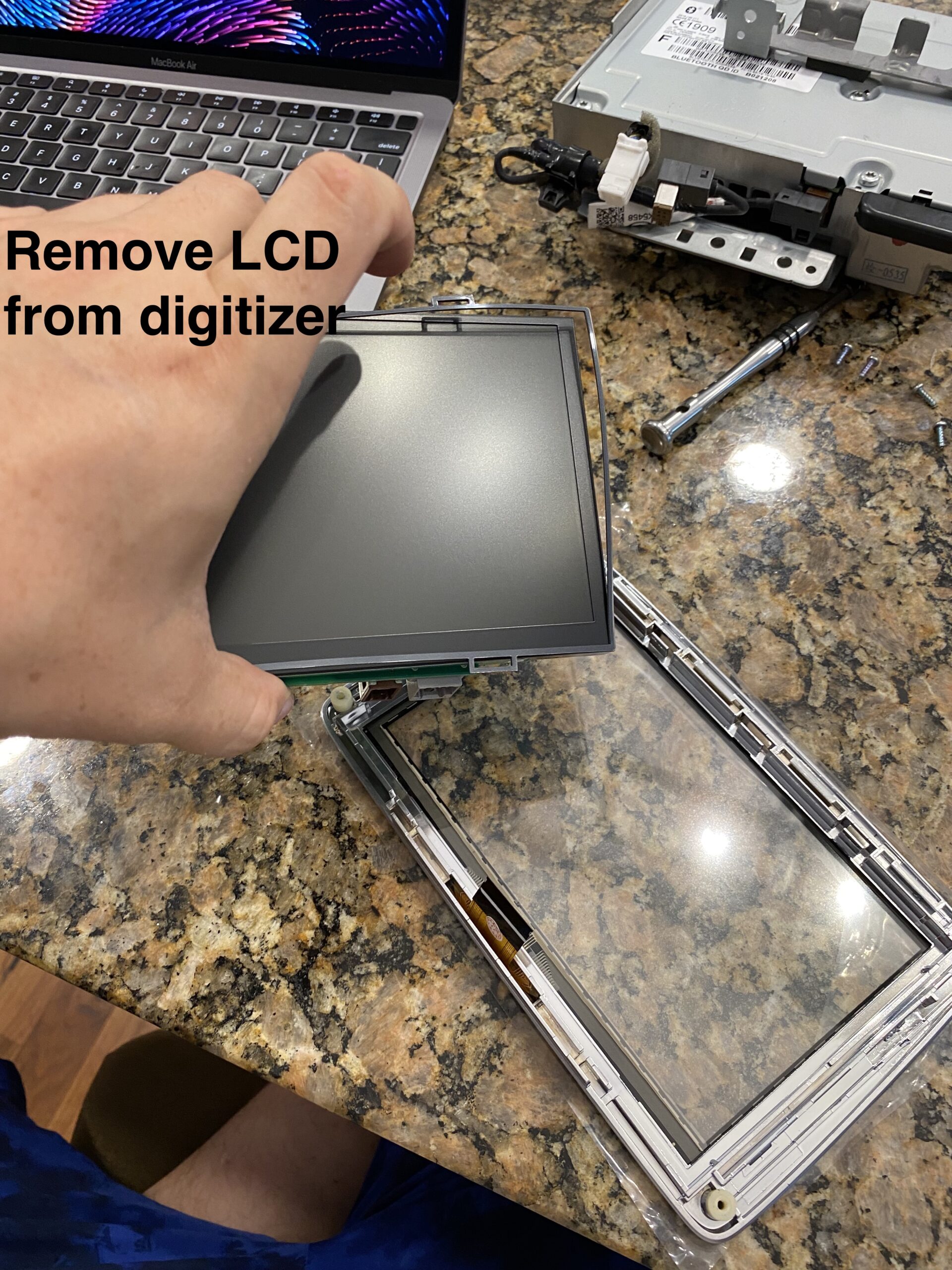
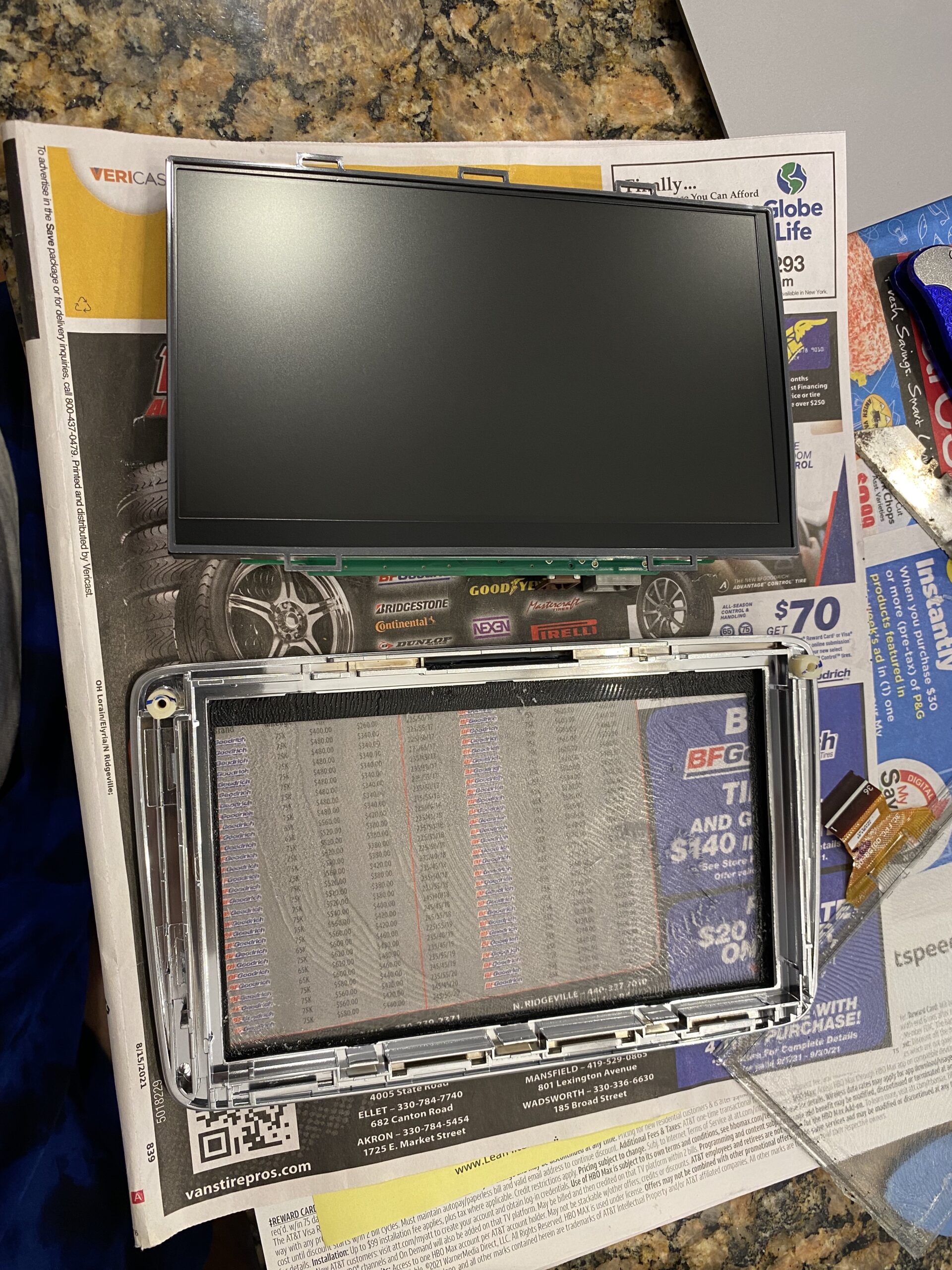
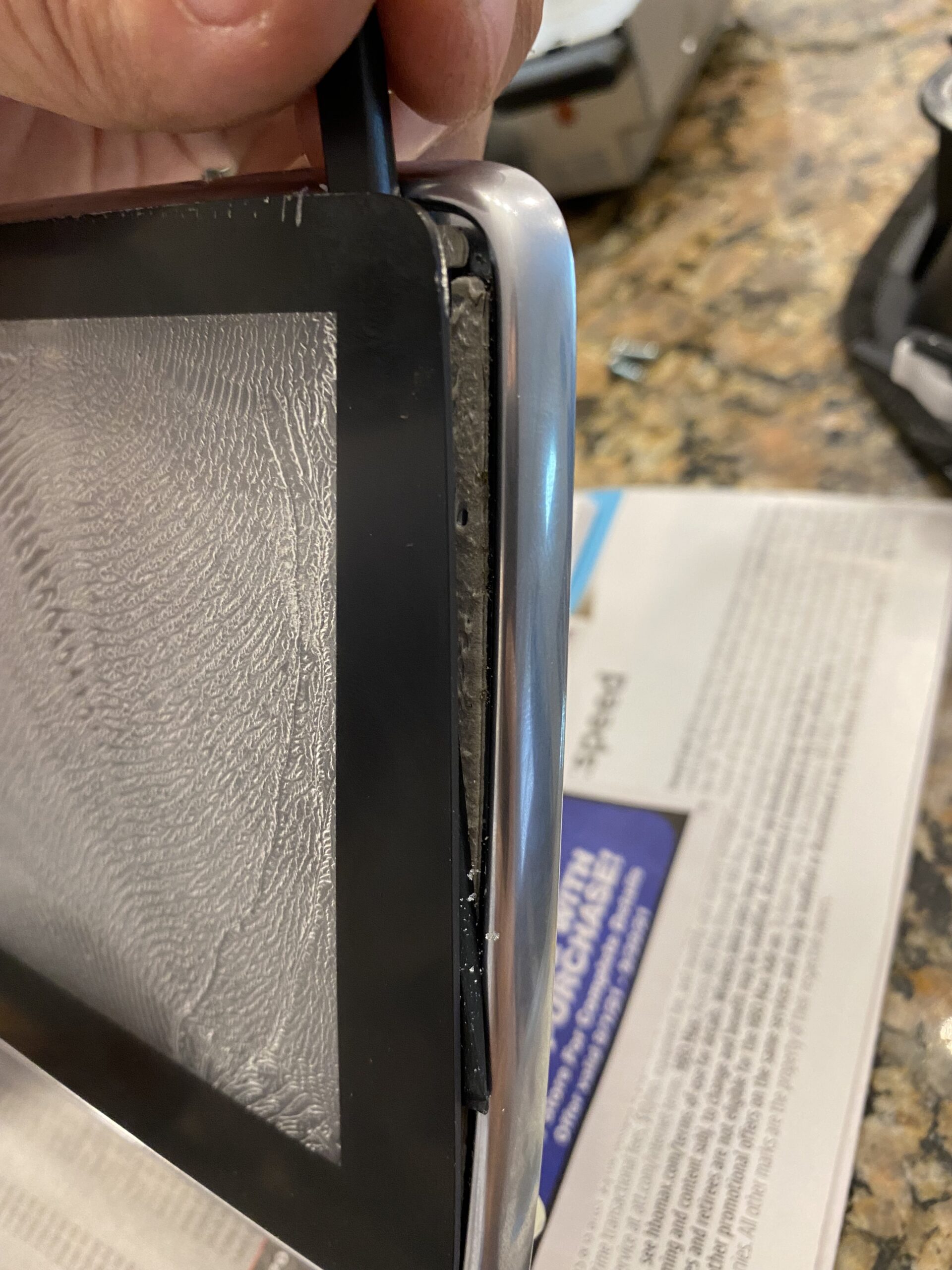
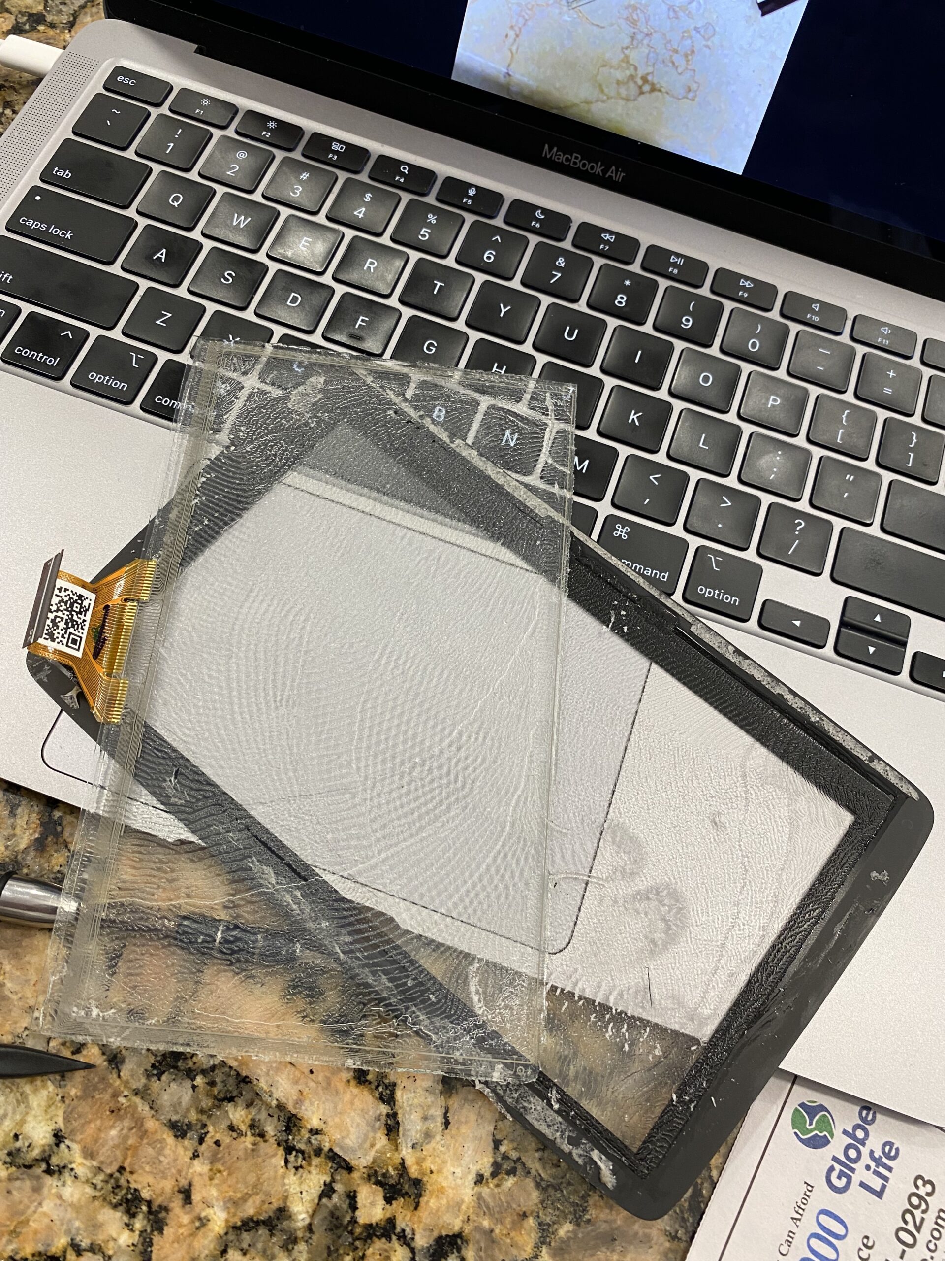
Work slowly when separating the old digitizer from the display assembly. Use heat carefully if needed to soften the adhesive.
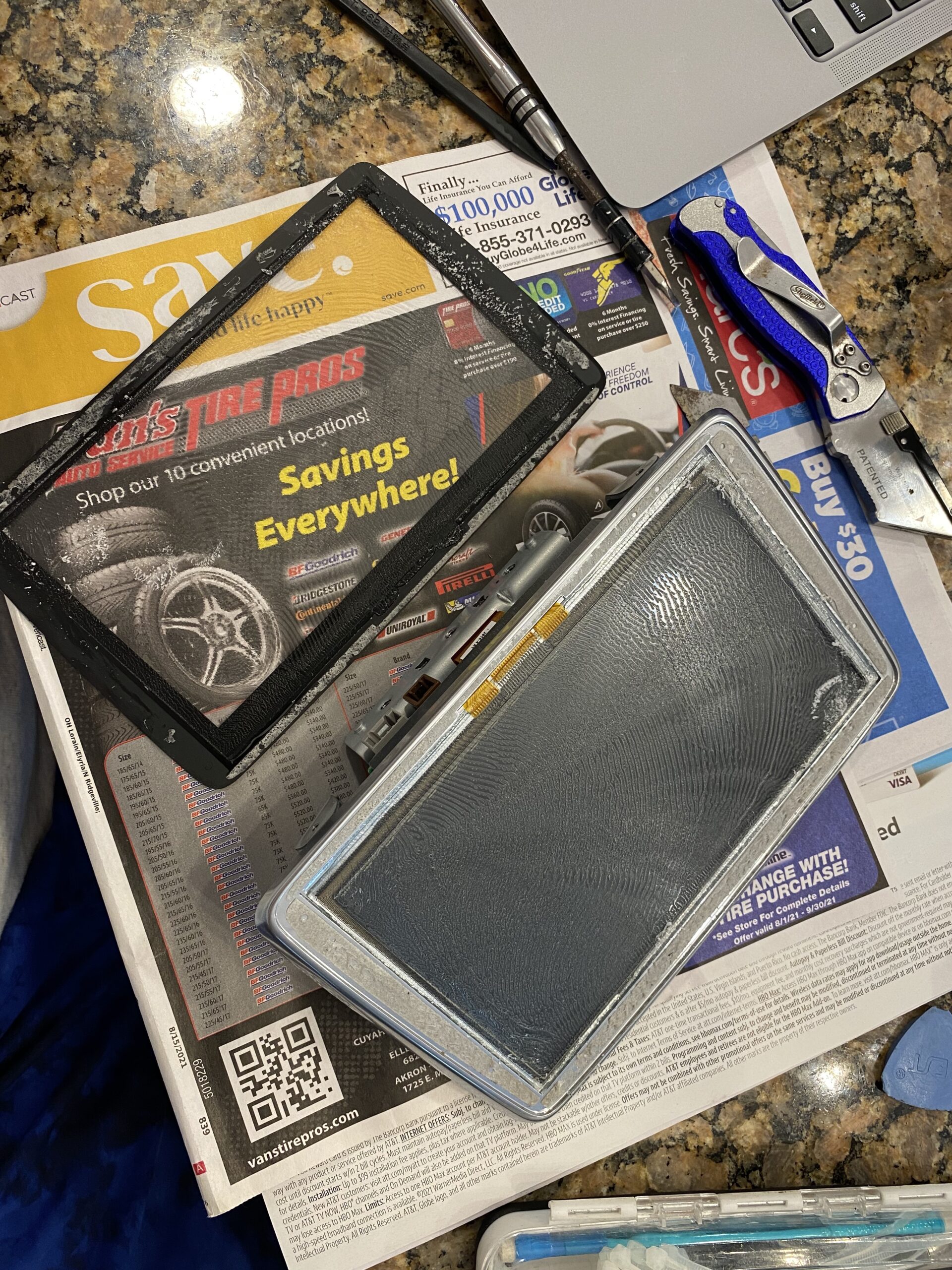
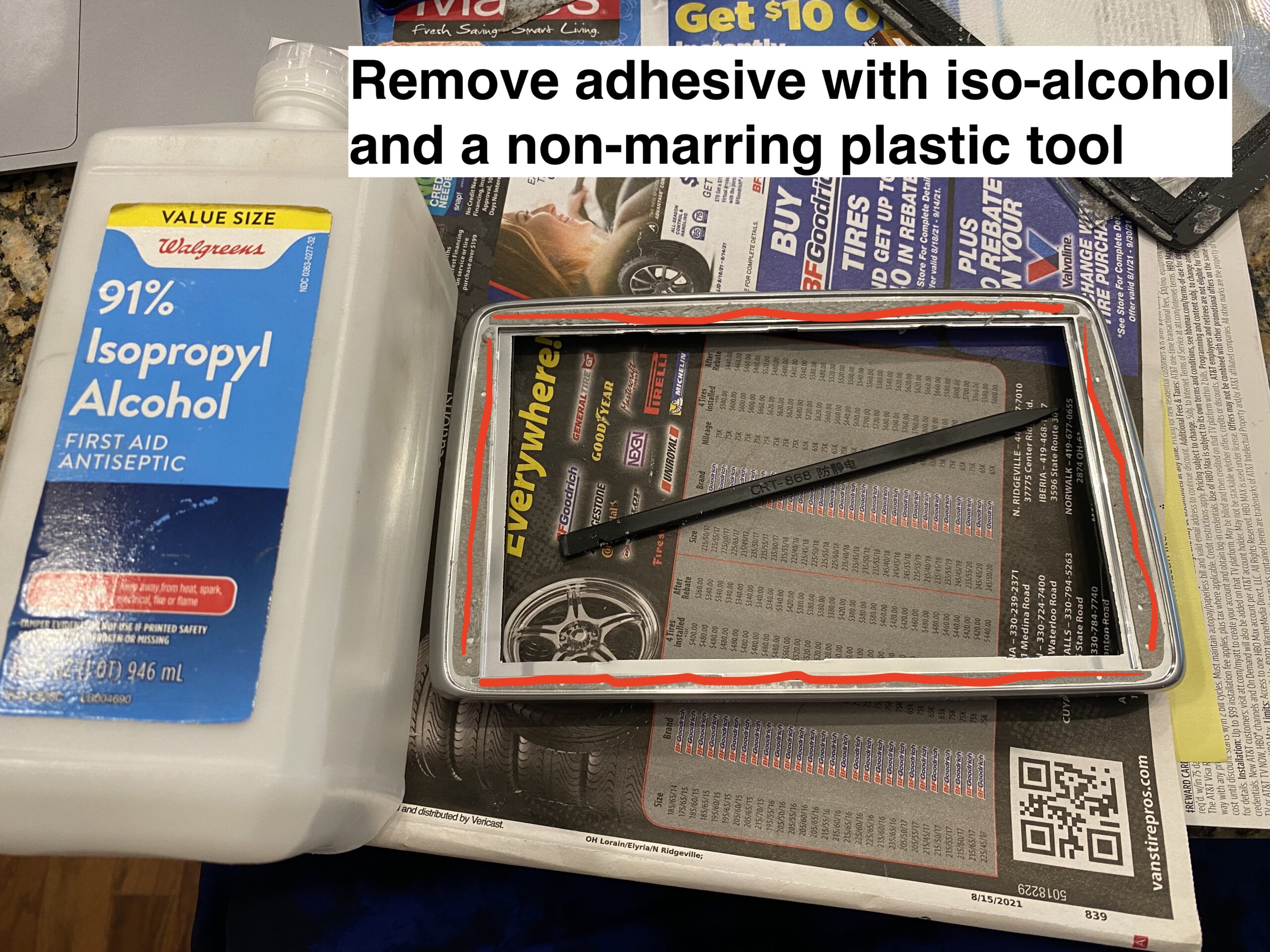
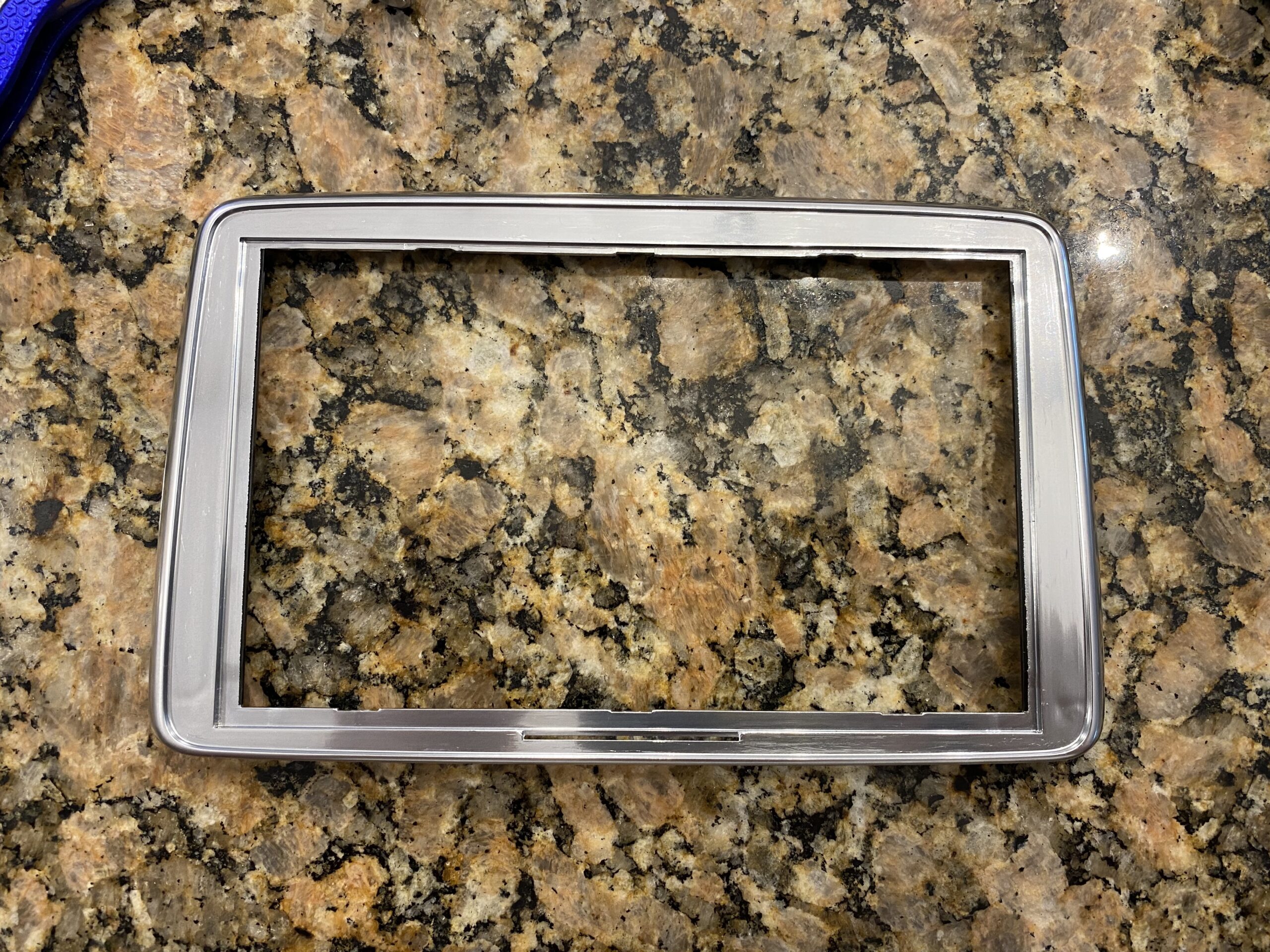
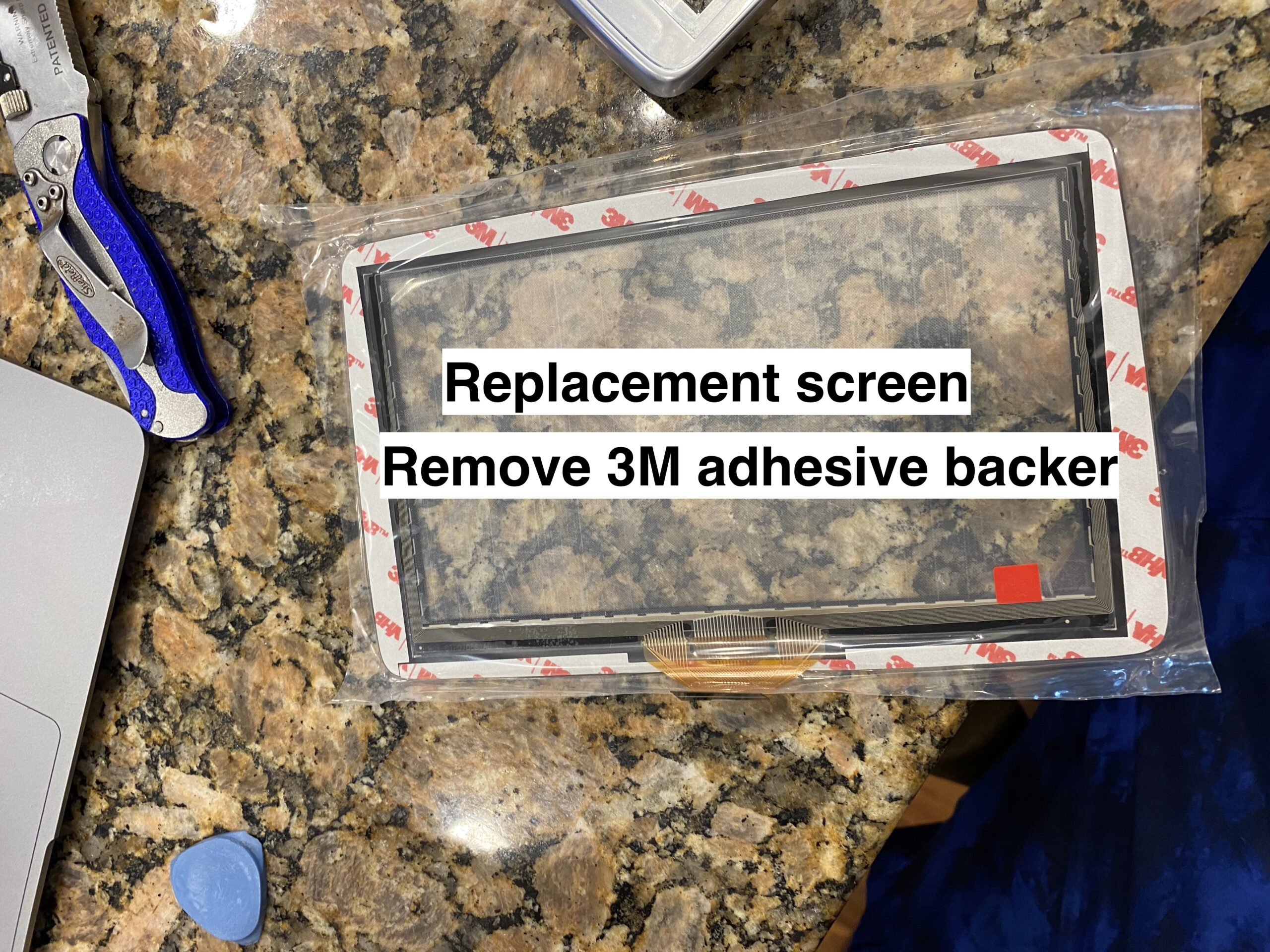
Remove all remaining adhesive and debris so the new digitizer can sit flat and bond properly.
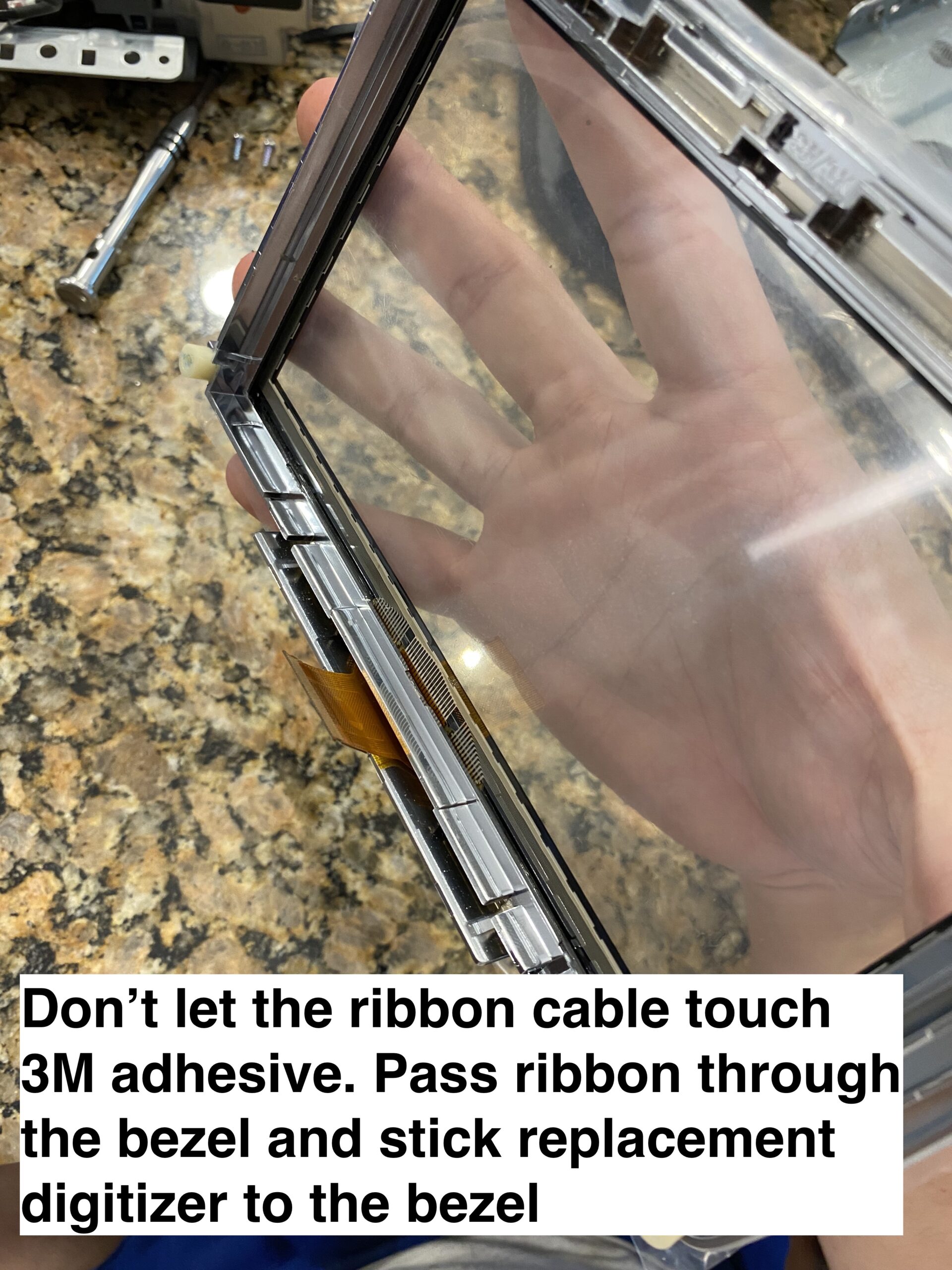
Align the new digitizer carefully, route the ribbon correctly, and make sure the assembly sits flat before reassembly.
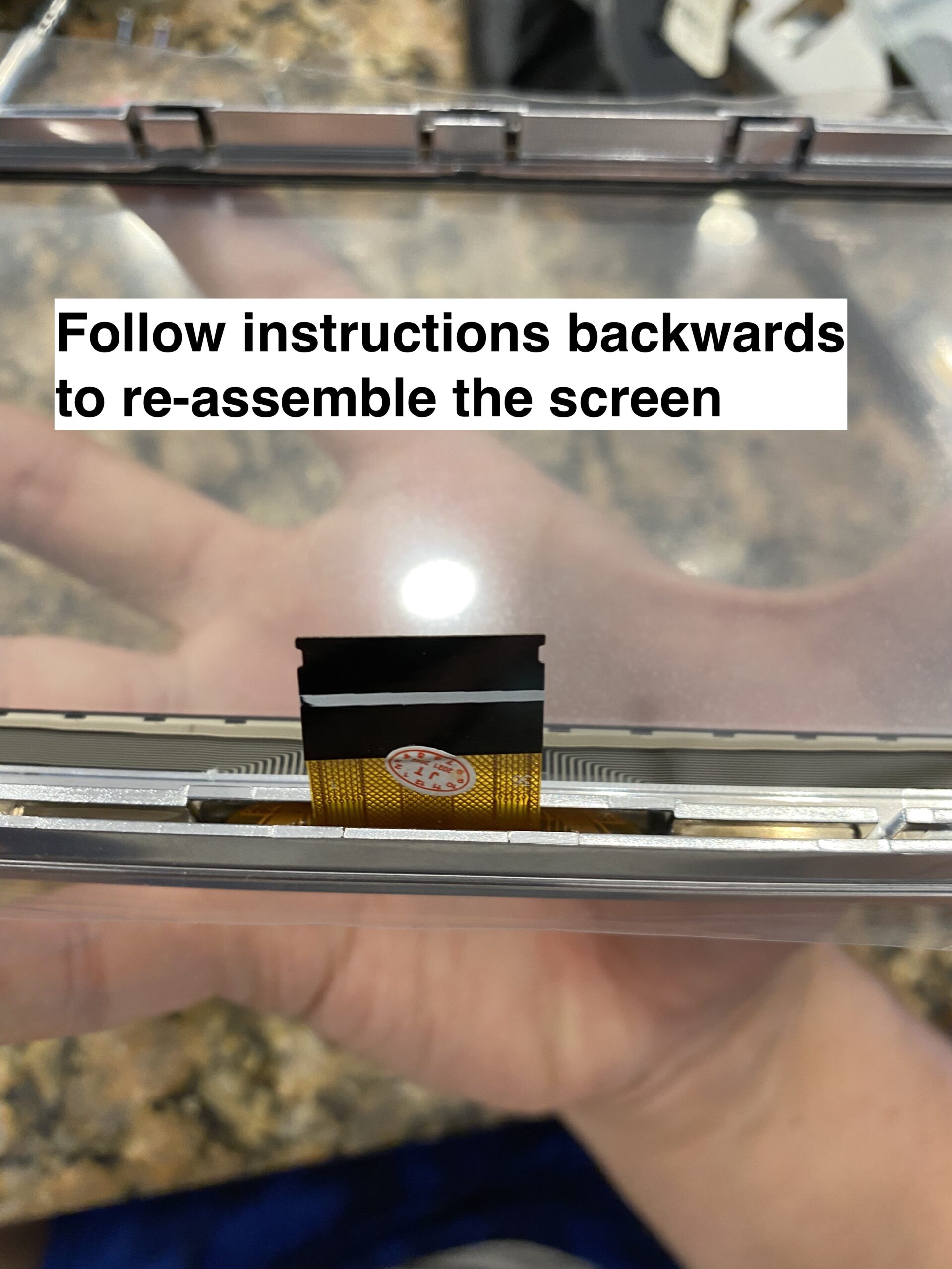
Reconnect everything, test touch response before fully buttoning it up, and then reinstall the trim pieces.
If your Mazda Connect screen is cracked or suffering from ghost touch issues, replacing only the digitizer can save a significant amount of money compared to replacing the full infotainment unit.
The most important step before ordering is confirming whether your screen uses the older 36-pin digitizer or the newer 50-pin digitizer.
This guide will quickly give you very important information you need on provisioning VVX phones with FreePBX
When a phone is factory reset, it will get a DHCP lease.
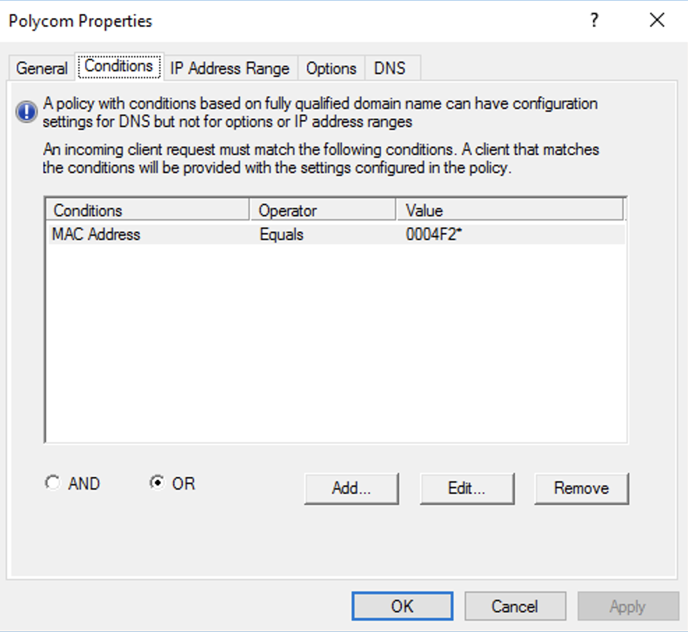
Polycom VVX phones have a mac address starting with 0004F2. You can create a policy in Windows DHCP server to allocate specific IPs to the phones
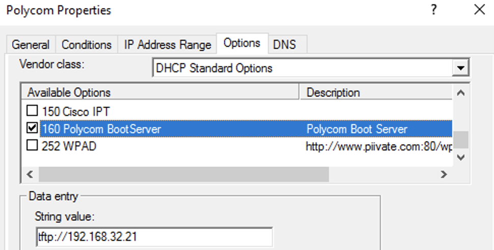
Polycom phones utilize DHCP option 160 to find a provisioning server. The contents of option 160 must be in string format. (e.g. tftp://192.168.1.10)
For time synchronization, DHCP option 42 must be set.

They also use DHCP option 002 to get the time offset. 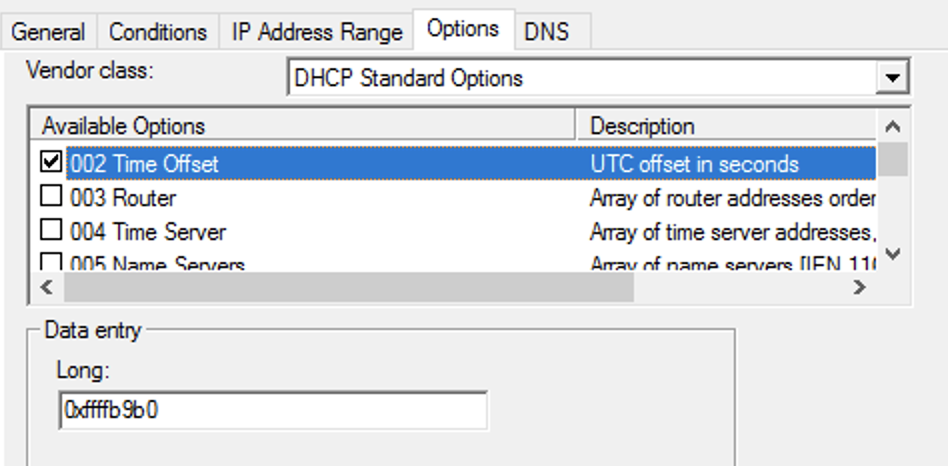
I use software called Tftpd64 to create a tftp server on my windows PCs. I tell it which folder I dump all my config files into.
when the phone boots, it will look for [mac address].cfg, if it can’t find that, it will look for [mac address]-web.cfg, then 000000000000.cfg.
000000000000.cfg is supposed to be the catchall for phone provisioning. It should not contain any actual phone provisioning commands, it only helps the phone point to other configuration files.
Polycom recommends using XML Notepad by Microsoft to edit these files.
000000000000.cfg defines the following settings before the phone boots:
This is an example deployment scenario:
The following settings are important for a FreePBX Deployment
msg.mwi.1.callBackMode=”contact” – This is part of the fix for the voicemail button. By default it is set to “register”, but FreePBX requires SIP phones to call a number to get voicemail
voIpProt.SIP.AlertInfo.1.value=”Auto Answer” – When a user dials *80[ext], typically the phone will autoanswer. This is known as page/intercom mode. Special SIP headers are sent by FreePBX so the phone recognizes a page from a regular call. Setting this will make the phone aware of a page
voIpProt.SIP.AlertInfo.1.class=”ringAutoAnswer” – your polycom phone has profiles that define what ringtone to use, how many times to ring, and to auto answer. This setting will tell the phone to auto answer if the SIP.AlertInfo field equals “Auto Answer”
attendant.resourceList.1.label=”Page All” – I have my main page group set to 900 in FreePBX -> Applications -> Paging and Intercom -> Page Group. These commands will create a softkey button to page all phones in page group 900.
attendant.resourceList.1.address=”900″
attendant.resourceList.1.type=”normal”
msg.mwi.1.subscribe=”[ext]” – enter your sip extension here to get the mailbox to work
msg.mwi.1.callBack=”*98[ext]” – enter *98 and your sip extension here. This is the number that is called when the voicemail button is pressed.