Category Archives: Uncategorized

WARNING Do not do business with D. Bren Photography or David Brendorfer

I was scammed $220 out of selling my Canon 5D Mark III in Brunswick, Ohio.

He left without paying the full amount I asked for the camera and now has the audacity to say that I scammed him!

Do not sell camera gear to this person, do not do business to this person, he isn’t a true photographer, he is a shady scam artist who acts on his own indulgences.

His contact number he used was: (440) 796-4884

Camera serial number 288022001868 5D Mark III


Enabling WiFi on Screenly OSE [Digital signage for Raspberry Pi]

Screenly is a preconfigured port of Raspbian, a Linux distribution for Raspberry Pi devices.

In Screenly’s FAQ, they say console login and wifi aren’t recommended, but in this tutorial, we will show you how to do all that.

1. Hook up a keyboard to your Pi while screenly is booted

2. Press Ctrl+Alt+F1 to open a terminal

3. Enter credentials pi | raspberry

4. Follow this guide to set up wifi normally

5. Reboot and it should connect, verify by going into the console and typing ifconfig

Some other info:

  • It appears Screenly uses UZBL, a webkit web browser to display webpages.
  • After getting into the console and logging in, you can do run startx, this will open the screenly application. Pressing Windows key+ D will get you to the desktop.
  • Screenly uses a lightweight DE called black box.
  • Right clicking the desktop will give you a couple extra options.

2015 Macbook and iPad Pro model numbers revealed

Didn’t see this anywhere else on the internet, it seems I just found these model numbers

2015 Apple Macbook

  • Input voltage (USB-C) 14.5V 2A
  • Model: A1534
  • FCCID: BCG-A1534

Suposed iPad Pro

  • FCC ID: BCG-A1489
  • Model Name: A1622, A1623
  • Input voltage: 20V 4.25A, 5V 1A
  • Interesting note, it looks like the iPad Pro may have USB type C for charging instead of lightning.

Apple Watch

  • FCC ID: BCG-E2871
  • Model Name: A1554, A1638

Other things

  • APPLE WATCH MAGNETIC CHARGING CABLE
  • MODEL NUMBER: A1570
  • Magnetic Charging Case
  • Model number: A1647
  • APPLE WATCH MAGNETIC CHARGING TRY-ON CASE
  • MODEL NUMBER: A1668
  • APPLE WATCH MAGNETIC CHARGING CABLE FOR DISPLAY CASE
  • MODEL NUMBER: A1667

Waves MaxxAudio on Dell Workstations

This post will be a bit of a rant. I recently got a Dell Precision M4800, a professional mobile workstation.

It comes with software preloaded called Waves MaxxAudio, it provides some of the same features other notebooks include that can “make audio sound better”.

I’ve been comparing the sound output with MaxxAudio enabled, and MaxxAudio disabled. And while it does sound somewhat better while on. The audio still sounds terrible for some strange reason.

I turned the audio enhancement off, and the audio that came out sounded like a megaphone. I  instantly knew something was up. So I stuck the audio from the headphone jack straight into a calibrated audio spectrum analyzer and found that:

1. When MaxxAudio is ‘off’, It isn’t actually off. The mids are boosted, and bass/treble cut off to make the audio sound much worse than it should be

2. When MaxxAudio is ‘on’ It boosts the bass and treble to levels where music begins to sound nothing like what it was intended.

So what I did next was uninstall the realtek driver, and rebooted my PC. Music sounds much better now, not distorted, and full of adequate sub bass that i’m used to hearing from a semi-decent DAC.


Now, I really expected better from Dell. I find this completely unacceptable in a professional notebook. Audio coming out of the speakers, when audio enhancements are “off” should not be tampered with at all.

My advice is, UNINSTALL THIS CRAPWARE the moment you get it. Use the stock driver provided by microsoft. Wave audio’s enhancement software is nothing but a scam and a battery/CPU hog.

This is the only way to make the speakers and headphone jack sound normal again.


VSX-822K Telnet interface

One of my new projects is figuring out how to automate my Pioneer VSX-822-K AVR. There have been posts before on how to do this with telnet for higher end AVRs (VSX-1022). But there doesn’t seem to be any documentation on mine.

My plan is to make a PHP web interface for controlling it because:

1. The Pioneer Control App for Android is laggy and crappy

2. I can control it from a web browser as well

The VSX-822-K uses port 8023 for telnet commands. Only some of the commands that worked with the VSX-1022 worked with the 822. Many of the function commands are changed. I went through every possible FN combination below. This information doesn’t seem to be available anywhere else but here.

Function number:
01FN CD
02FN Tuner
04FN DVD
05FN TV
06FN Sat/Cbl
10FN Video H
15FN DVR/BDR H
17FN iPod/USB
25FN BD H
33FN Adapter
38FN Netradio
41FN Pandora
44FN Media Server
45FN Favorites
49FN Game H

TO get the rest of the commands like tuner preset+/-, I installed Shark for Root on Android. This application is like WireShark in that it captures packets to and from the device. I then opened the AVR application and made sure I pressed every button that was available.

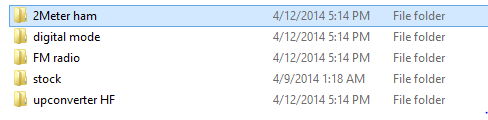
But then I remembered that the app downloaded device specific data when I first opened it. I went on a hunt inside ESFileExplorer for the related application files. I found them in /data/data/jp/pioneer.avsoft.android.controlapp
I zipped that up for inspection.
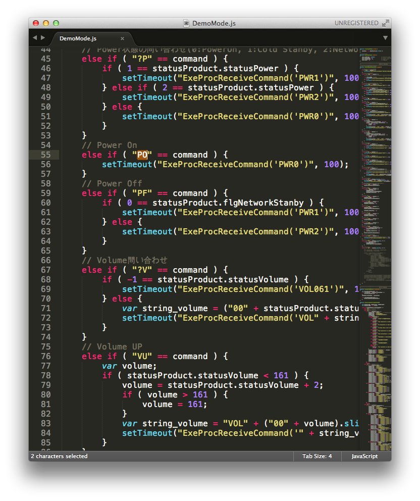
And then I found the jackpot
Screen Shot 2014-01-03 at 2.56.30 AM


Every command the AVR uses, implemented in HTML and JS, by japanese programmers at Pioneer Electronics. I can’t blame them for using HTML, It’s easy, but it’s not responsive at all. No wonder the app was laggy.

After sifting through the code, here’s what I got out

?RGD ReceiveGenerationInfo
?RGF ReceiveEnableInputFunctionInfo
?RGC ReceiveNetworkStanbyInfo
?PWR ReceivePowerStatus
	Values:
	PWR0 Power on
	PWR1 Cold standby
	PWR2 Network standby
?VOL ReceiveVolumeStatus
?MUT ReceiveMuteStatus
	Values:
	MUT0 Mute on
	MUT1 Mute off
?FN ReceiveInputStatus
?ICA ReceiveiPodFunctionInfo
?GAP Prints OSD info
?GEP ReceiveDisplayInformation
?GDP ReceiveListAndLineInformation
?GCP ReceiveScreenInformation

Function number:
FU: Function up
FD: Functon down
01FN CD
02FN Tuner
04FN DVD
05FN TV
06FN Sat/Cbl
10FN Video H
15FN DVR/BDR H
17FN iPod/USB
25FN BD H
33FN Adapter
38FN Netradio
41FN Pandora
44FN Media Server
45FN Favorites
46FN AirPlay
47FN DMR (doesn't do anything?)
49FN Game H

Power Mode:
PO Power On
PF Power Off

Volume:
VU Volume Up
VD Volume Down
MO Mute On
MF Mute Off
MZ Mute toggle (doesn't work?)

FM Presets:
##PR (30 avail)

Surround Sound:
0100SR Advanced Surround
0005SR Auto/Direct
0010SR ALC/Standard

Buttons:
10PB Play
11PB Pause
12PB Skip Reverse
13PB Skip Forward
20PB Stop
30PB Enter
31PB Return
40PB iPod Control30

Some other things to note:

The AVR only allows one telnet session at a time, otherwise it will refuse the initial connection.

The remote is a huge pain in the ass to use, if you want to change settings you have to go into the internet radio function menu, just to get the 80’s style menu to open.

What’s worse is the menu goes from digital in the CPU, to analog in the DAC (so it can be outputted to composite video), THEN it gets converted back to digital for use in HDMI. It looks really ugly to say the least.

Tips for using SDR#

Intro

  • When you are using SDR# you are looking at a chunk of radio spectrum. Standard radios only have the ability to process one signal at a time, you now have the ability to not only hear, but also see the signals.

 Sample Rates

  • Your sample rate is your bandwidth. If you only want to see 1MHz of spectrum, choose 1.0MSPS. Higher sample rates above 2.4MSPS are not recommended
  • sample rate

 Interference

  • Interference from very strong signals will show up as mirrors that run in the opposite direction of the actual signal or only appear at the edge of the screen.
  • oposite
  • disappear center


  • Interference from very strong signals will show up at intervals corresponding to your MSPS rate
    • If you have a signal at 100MHz, and your sample rate is 1MSPS
      • You will see a duplicated signal at 101MHz, 99MHz, 98MHz, and 102MHz.
    • If you have a signal at 100MHz, and your sample rate is 2MSPS
      • You will see a duplicated signal at 98MHz, 96MHz, 102MHz, and 104MHz.

 The two display methods of SDR#

  • What is the FFT and Waterfall?
    • FFT: Top half of the screen
    • Waterfall: Bottom half of the screen

 How to enter frequencies into SDR#

  • Frequency entry
    • Type it into the VFO
    • typing
    • Click on the bottom or top half of a number
    • updown
    • Drag the waterfall or FFT
    • dragging
    • Use your scroll wheel

 Eliminating the center signal spike

  • If you want to get rid of that DC spike in the center, enable Correct IQ
  • correctiq

 Decoding digital tips

  • For decoding digital signals
    • max out the volume, use WFM, change frequency step to 6.25KHz, and change the bandwidth to fit perfectly around the signal’s envelope.
    • env
    • Set your sample rate to .900000001 MSPS (I personally have had the best results with this)
    • Also uncheck the filter audio box, chances are, your application will want a clean signal coming from SDR# to decode digital data properly.

 Decreasing latency

  • If you are decoding time sensitive information (Trunked radio decoding), turn down your audio latency so it is low enough to where the audio doesn’t pop from buffer underruns, but is fast enough so that the beginning of conversations aren’t cut off.
  • audio digital

 Keeping things organized

  • If you are going to be using your SDR for multiple uses, like HF, VHF, and Digital. Duplicate your SDR# folder for each instance. This will save configuration time, so you won’t have to change modulation, volume, or Gain every time you want to listen to different modes.
  • copies

 When to use AM

  • If you do not have an upconverter, there are only very few times you will use AM,SSB,USB,LSB,DSB,CW,or RAW. These include
    • Listening to Airband (120MHz)
    • Listening to CB Radio (26-27MHz)
    • 12 and 10meter ham bands (24-30MHz)
    • Low tech gadgets that run on 27 and 49MHz (RC Cars)
    • Remote controls that run on ~400MHz (Car door unlocks)
    • some low tech ISM devices 902-928MHz (home automation, weather sensors)
  • Otherwise use NFM or WFM

 Common interference in the home

  • If you use Wi-Fi or Ethernet in your home, you may see lots of interference in the 140-160MHz range, when browsing these ranges don’t use Tuner-AGC unless you have already locked onto a signal you want to listen to. If you are just browsing, keep the gain somewhat low to avoid overloading the device.

 AGC

  • When to use AGC
    • Use AGC when you are aware that checking the box may lead to visible interference, only use AGC when you are sure the frequency you are on, is the only signal you want to listen to.
  • Tuner-AGC seems to work better than RTL-AGC at picking signals out from noise

 Calibration

  • RTL-Calibration
    • Generally RTL sticks need calibration. If you are only listening to FM Radio, calibration probably isn’t needed, but for narrow and more precise signals, it is required.
    • It is recommended to wait several minutes before calibrating, when the temperature of the dongle warms up, the frequency could shift 4+ppm.
    • Calibration is calculated in ppm (parts per million) AKA Hertz per MHz
    • so, if your correction is 50ppm, a signal at 1,000,000Hz(1MHz), will be 1,000,050Hz(1.00005MHz)
    • Remember that this scales the higher in frequency you go. So at 900MHz, the correction will not be 900,000,000/900,000,050
    • It will be 900,045,000. At 900MHz, a difference of 45 KHz is huge, especially for narrow signals like voice.
    • When calibrating your dongle, always opt for using a higher frequency reference point.
    • Calibrating to a local NWS station (162MHz) is good, but calibrating to a local GSM tower, or trunked radio control channel is much preferred.
    • calibrate

 Getting a clearer picture

  • FFT Resolution
    • If you are listening to narrowband signals, it may be helpful to get a clearer view of the signals you are looking at.
    • fft res
  • When you first start using SDR# turn your contrast down to a level where:
    • no signal = blue
    • weak signal = light blue
    • med signal = orange
    • strong signal = red
    • Note, while gain controls how the signal is heard and viewed, contrast is only visual.
    • contrast


Log Recorder update

Log recorder has been updated to version 3.0

What does log recorder do?

  • Records each call from DSD for archival purposes
  • Logs each call in a database YYYY/MM/DD/UNIXtimestamp TGID RID.mp3

Changelog

  • rewritten in PHP
  • rewritten in preparation of the abandonment of SDR# in favor of Unitrunker
  • utilizes sdrsharptrunking.log instead of single.log, so SDR# doesn’t need to be run
  • Multiplatform (needs php5 and sox for Linux support)

Download

Eliminating interference in RTL-SDRs

I oftentimes see people asking why there is so much interference on their SDRs. Most visible interference is in fact not caused by real signals, but caused by the RTL dongle overloading.

Eliminating visible interference

The first to troubleshooting interference is turning off any type of AGC. AGC maxes out the gain slider which makes nearby strong signals to appear where they shouldn’t be.

37.2 dB is a good level

Turning on and off AGC, Manual Gain 37dB

Turning on and off AGC, Manual Gain 37dB

Change your sample rate. Understanding the sample rate is quite easy. 0.25 MSPS will only show 250khz of spectrum on your waterfall/FFT screen.

It isn’t recommended to use 0.25 MSPS because this can cause interference on frequencies every 250KHz. Take for example, a frequency on 850MHz and 850.250MHz. If you set your sample rate to 0.25MSPS, and either the signal is too close, or your gain is too high. Both 850MHz and 850.25 will mix causing bad decodes. The same can be found up to 10 iterations of 250KHz past the original signal. To see this, find a strong signal, set your gain high. Center it on your waterfall/FFT display, and increment the frequency by 1MHz. You will see the same signal every 1MHz, slowly decreasing in strength as you increase the frequency. Now use 2.048MSPS, you will notice mirrored interference every 2.048MHz

250KHz interference

250KHz interference, 929.6125 MHz signal

.9000001 MSPS is recommended for digital modes because it provides a small enough chunk of spectrum for visually inspecting the signal, and it doesn’t cause even overlaps. So instead of 849MHz, 849.5 849.75 interfering with 850MHz, interference will only occur every 900KHz, which has a lesser chance of overlapping interference.

How to eliminate real interference

Real interference is caused by any type of RFI near your SDR receiver. Simply moving the dongle and antenna away from the source of noise (computer, TV. AVR) will lower interference.

To go even further, you can add a ferrite core, or an RF shielded case around your SDR to block unwanted signals.

RTL-SDR Enclosure


RTL-SDR scanner/decoder/logger/recorder

A few months ago I wrote a simple script in batch that allowed me to record each call in MP3 format with the TGID, RID, date recorded, into a folder that contained the proper year/month/date.

It’s still a little buggy, there are much better ways of doing this.

But what I recently did was make a web front end to read the folders and files, then spit out a table with all the data.

Right now it’s not very efficient, but I plan on fixing that by migrating from, a loop that scans every file from a directory, to a database application. I’ll be using a program called Everything Search by Void Tools. I chose this because it has an extremely fast indexing engine and a command line interface.

This should speed up my page load times by a lot. With my current setup a query takes about 5 seconds, with a directory that has a month of calls, 26,000 files, and almost 1GB of file space taken. If I don’t make this change, page load times will only increase.

I hope to be done with this migration by the end of the week.